How Do You Keep Homeruns Straight in a Commercial Panel?

Status
Not open for further replies.

George Stolz

Moderator
Staff member
Location
Windsor, CO NEC: 2017
Occupation
Service Manager
I'm working in a hospital, the electrical room we're currently installing has 7 panels. Generally, the circuits in each conduit that enter a panel are written with a sharpie next to the connector where the circuits enter.

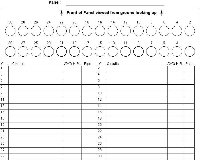
Since in this case several of the conduits are carrying as many as two full MWBC's apiece, I was thinking of suggesting we use something like this on a clipboard next to each panel.
PanelConduitDiagram.jpg


Thoughts?

Edit to add: So, as home runs are brought into the panel, the person would write on the schedule like this. In the example, the right rear knockout contains 1,3,5 on one neutral, and 7, 9, 11 on the other neutral.

What do you do?
 
Last edited:
Seems like a neat idea. I would make the front face down, personally, I think it would make it a little easier to keep straight. (30 would be left rear, 1 right front)
 
Maybe I read your link wrong, but it seems as though you want the home runs to cross inside the panel in your example. You've got 1,3,5 and 7,9,11 (left side breakers) leaving out of a right side pipe. Did I read that right?

Seems like a decent enough idea, but I wonder what particular troubles you're having with the present system of just writing on the pipe or the inside of the panel?
 
Last edited:
Yes, you read it right Marc. It was just an example, and 1 - 13 came to mind first. :)

John said:
I would make the front face down, personally, I think it would make it a little easier to keep straight. (30 would be left rear, 1 right front)
I was thinking when you're standing at the panel, it's literally taller than I am. So, looking up at it seemed to make more sense.

If everybody else feels John's right on this, I'll flip it before I make the suggestion. :)
 
georgestolz said:
Ah, somebody brought in their kindergartners to write circuit numbers on things. :wink:

How does your form allow for panels with three layers of pipe or panels with pipes of varying sizes? Seems like a good form for a branch circuit panel with all 3/4.
 
Why wouldn't you just use brady tags to number the conductors instead of labeling all of the pipes? And dont you think that your clogging the center of the panelboard where your main is going to be terminated. 30 3/4" pipes seems excessive but is that in the specs.
 
wirenut25 said:
Why wouldn't you just use brady tags to number the conductors instead of labeling all of the pipes?
I'm assuming Brady Tags are numbers directly on the conductors? We do, but if they fall off or get accidentally cut off before landing the conductors, having the numbers written inside the panel seems like a good back-up plan. And I've found it to be a good view of the conductors at a glance, when terminating, IMO.

30 3/4" pipes seems excessive but is that in the specs.
I don't think they were that specific. I know when I walked out the door on Friday I had forgotten to count the holes, but I know there was a heap of them. 30 was about all I could fit on a page. :)

mdshunk said:
How does your form allow for panels with three layers of pipe...
It doesn't, even when sketching - it was too many pipes for a sheet. I should probably fix that somehow.
 
Panel Labeling

Panel Labeling

Well its all how you see the apple, then one also has to consider what the present home runs look like, what is the clients way, but I assume all this
work has been completed to this point.
Nickel to a dime the conduit will get painted, so the conduit markup is history. There are many variables that will quickly change your desired application of the wire being labeled. Frankly if that?s what it looks like fine, tape the legend and the circuit listing, I'd remove the number from the number from conduit / circle layout and leave a blank space.
I know I usually have to run for example Odd number service(s) from an area and usually run home the same way. Even / odd service sets together and
line up prior to there respective side of the can, (where possible) this line up is usually made long before your present conduit in Can. And of course not
crossing over just to make it to right or left side...(( I can hear the crowd))

I do like: using the Brady machine, as mentioned, and will use painter blue tape (pre termination) same as drafting tape, then number accordingly. I've even put numbers on the circuit as it enters the can and later on the horizontal part at each circuit.

Why don't you have 42 spaces, where that arrangement. Wheres the "Fed from Statement" per panel? Does the Spec's allow combined home run for
multiple services based on a 30 or 42 space can ? You sure there are no
bigger conduits coming out of the top of these cans ? Just some of my
thoughts having seen your post.
 
George no offense meant but as a foreman I would say 'WTF' if I saw someone wasting time with charts and graphs.

Tag the groups and move on, if your tags are falling off I suggest that whoever is putting them on the wires is handling the adhesive side to much.

If someone is cutting the tags off they need a dope slap and a new assignment then cutting panels in.

JMO, Bob
 
iwire said:
if your tags are falling off I suggest that whoever is putting them on the wires is handling the adhesive side to much.

Not always the case. I recently bought 2 books from my favorite supply house that just wouldn't stick. Exposure to high humidity here is a real problem.
 
chris kennedy said:
Exposure to high humidity here is a real problem.

Move to a less humid state. ;)

Yeah and if they are old they will be junk as well.

Through em out and get new ones.

Of course if wire lube was used all bets are off as far as getting anything to stick.:D
 
JohnJ0906 said:
I would make the front face down, personally, I think it would make it a little easier to keep straight.
georgestolz said:
I was thinking when you're standing at the panel, it's literally taller than I am. So, looking up at it seemed to make more sense.

If everybody else feels John's right on this, I'll flip it before I make the suggestion. :)
My opinion on this is to view the conduits/connectors as you would see them when standing at the panel, from inside the can. For conduits coming from overhead, the front on top, 1 on the left; for conduits coming from below, the front on the bottom, again 1 on the left.

As for a standardized chart, except when pulling your own holes, it might be more accurate to print out PDF's or other manufacturers' drawings of can top and bottom panels. Besides, as Marc pointed out, how often does a panel have every conduit the same size and placement?

Your drawing with the red markings points out that pre-drawn charts are not really worthwhile, but the field-drawn charts are a good idea. You can tuck them in behind the schedules or leave them inside the cans (if not a hazard).
 
George, in all honesty, I think you're putting too much thought into this. And no, I'm not just saying that because Bob did and he's a foreman. ;)

Any system you come up with is quickly going to get tossed out the window because you won't ever be able to be that precise. And if you try, you'll end up going nuts and like Bob said, you'll be told to slap the pipe in and move on.
 
quogueelectric said:
32,34,54?? is this a 2 section panel?? i do understand 54 is a c phase

I'm suprised it took this long for someone to notice. :)

Yeah, I'll be working that kind of thing out, by and by. I sought out confirmation in a recent thread.

iwire said:
George no offense meant but as a foreman I would say 'WTF' if I saw someone wasting time with charts and graphs.
Well, at least I'm thinking about it off the clock. :)

Peter D said:
Any system you come up with is quickly going to get tossed out the window because you won't ever be able to be that precise.
What is precise about it? I'm just shooting for a worksheet, not so much a work of art.

I'm thinking if I were alone, it would work out all right, but maybe involving others would just screw it up. It's reminiscent of something that happened in a couple houses. I had a system that worked out all right with just me and my helper, and we had a snazzy typed panel schedule with no extra effort required, I just had the info on my clipboard and typed it up on my own time.

I tried it in the next house, and the other team we were working with didn't stick with the system. So, not only did the typed panel schedule never happen, the homeruns also did not get labelled.

Maybe it was a stupid idea.
 
42 ckt max

42 ckt max

I have only installed one panelboard with more than 42 ckts in the last 30 yrs 2 winters ago, and that was a 1200 amp main custom buss detail built by the atlas switch company. There were 18- 3 pole breakers and of course I had to be the troublemaker who noticed this and saw that they had an underwriting laberatories sticker on it. I was also told by the project technician for the company that they get direct ul approvals. Here is the funny part the service was for Town Hall go figure that doesnt mean it was right but you cant beat town hall and they are the AHJ and the customer. Can I get an Amen!!
 
I think it looks like a great idea. The only change I would make would be to leave empty the top area where you have the conduits drawn in.

First of all you would be very hard pressed (if not impossible) to get 15 3/4" conduits in in each row of most panelboards.

Second, the empty area will allow for different size conduits and different spacing of the conduit to reflect accurately on the schedule.

Good work
 
Status
Not open for further replies.
Top