Dsg319
Senior Member
- Location
- West Virginia
- Occupation
- Wv Master “lectrician”

Wow, definitely have some learning to do with those, today is the first time I ever really noticed one as I’m use to just typically grabbing 24vdc and sending an input back from level switch directly to an digital input card in a PLC. Thanks for the info!It's a level translator between different digital levels on its input and output.
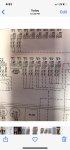
This is the schematic of your version of the module from the spec sheet:
View attachment 2555031
A logic "high" signal voltage input +- VDC across pins 1 & 2 will cause a current through the LED on top that is determined by the series resistor Rx. The light emitted by the LED is sensed by the bipolar phototransistor and turns it ON (the LED and phototransistor form an optoisolator because light is the only thing that connects them in any way). Then there is circuitry with hysteresis (INPUT VOLTAGE HYST. CIRC.) that converts the phototransitor output into a logic level voltage. Hysteresis creates a dead zone where you have to drive it an extra amount to make it change from its previous output state (high or low). This helps keep it from falsing on noise that may be present on the input.
Then that internal logic voltage is converted to a current that drives the input (base terminal) of the output NPN transistor on the bottom. The output of the module is the "open collector" of the NPN transistor. When the transistor is turned ON it draws DC current at pin 4 and pulls the voltage down near ground (pin 5). Usually the pin 4 OUTPUT is connected to load that has a "pull-up" resistor (or current source) which pulls up the output voltage when the transistor is OFF.
So basically the device is a digital logic level translator that's compatible with a wide range of input and output voltage levels, provides a high level of isolation, and has increased immunity to noise via hysteresis (aka a Schmitt trigger).
Great explanation/ response.It's a level translator between different digital levels on its input and output.
This is the schematic of your version of the module from the spec sheet:
View attachment 2555031
A logic "high" signal voltage input +- VDC across pins 1 & 2 will cause a current through the LED on top that is determined by the series resistor Rx. The light emitted by the LED is sensed by the bipolar phototransistor and turns it ON (the LED and phototransistor form an optoisolator because light is the only thing that connects them in any way). Then there is circuitry with hysteresis (INPUT VOLTAGE HYST. CIRC.) that converts the phototransitor output into a logic level voltage. Hysteresis creates a dead zone where you have to drive it an extra amount to make it change from its previous output state (high or low). This helps keep it from falsing on noise that may be present on the input.
Then that internal logic voltage is converted to a current that drives the input (base terminal) of the output NPN transistor on the bottom. The output of the module is the "open collector" of the NPN transistor. When the transistor is turned ON it draws DC current at pin 4 and pulls the voltage down near ground (pin 5). Usually the pin 4 OUTPUT is connected to load that has a "pull-up" resistor (or current source) which pulls up the output voltage when the transistor is OFF.
So basically the device is a digital logic level translator that's compatible with a wide range of input and output voltage levels, provides a high level of isolation, and has increased immunity to noise via hysteresis (aka a Schmitt trigger).