How ph shift 120* works

Status
Not open for further replies.

Malywr

Senior Member
Location
New Jersey USA
I know changing of coils of wire on transformer will change voltage but how do you change * on coils
I dont built transformer, motor or gen bu I wonder how that works.
63dd52c8bd8639aa2810cec0567c0f25.jpg


Great picture
Could someone explain how single transfer 3 PH and single transformer 1PH can have ph shift 120* how it looks physical

Another question to make stuff more complicated what adding capacitor to single PH do?

Sorry for picture quality I copped that from another feed and could not get better quality pic even original was perfect but hopefully you get idea


Sent from my iPhone using Tapatalk
 

Seven-Delta-FortyOne

Goin’ Down In Flames........
Location
Humboldt
Occupation
EC and GC
Phase shift comes from the coils on the generator being 120 degrees apart.

That is just carried through, from power lines, to transformer, to motors. 3 phase motor coils are 120 degrees apart.

A 3 phase transformer is really just 3, single phase transformers in the same enclosure.

Capacitors are usually added to single phase motors to get them started. Otherwise, there is nothing to begin rotation, because current is induced 180 degrees apart.

So you add a start capacitor to shift phase current 90 degrees during start up.

There are other uses for caps, like PF correction, but that’s not relevant.
 

Hv&Lv

Senior Member
Location
-
Occupation
Engineer/Technician
Jumping in the deep end I see...
It has to do with how the generator is wired

Here’s a simplified video.
 

Malywr

Senior Member
Location
New Jersey USA
Phase shift comes from the coils on the generator being 120 degrees apart.

That is just carried through, from power lines, to transformer, to motors. 3 phase motor coils are 120 degrees apart.

A 3 phase transformer is really just 3, single phase transformers in the same enclosure.

Capacitors are usually added to single phase motors to get them started. Otherwise, there is nothing to begin rotation, because current is induced 180 degrees apart.

So you add a start capacitor to shift phase current 90 degrees during start up.

There are other uses for caps, like PF correction, but that’s not relevant.

So once power is generated 120* it always is 120* ?
 

Besoeker3

Senior Member
Location
UK
Occupation
Retired Electrical Engineer
Capacitors are usually added to single phase motors to get them started. Otherwise, there is nothing to begin rotation, because current is induced 180 degrees apart.

So you add a start capacitor to shift phase current 90 degrees during start up.
That's one application.
But most I'm aware of in residential properties just single phase units. - capacitor start units are not that common.
 

Hv&Lv

Senior Member
Location
-
Occupation
Engineer/Technician
So once power is generated 120* it always is 120* ?
Yes and no. It’s really hard to explain in a paragraph or two.
One 120 degree leg goes to residential then it’s like the beginning of the video. The coils are 180 degrees apart.
Three 120 degree legs are used for three phase power, but power factor, unequal loadings, etc can cause the angles to change down the line.
 

Carultch

Senior Member
Location
Massachusetts
What about in the case of 120/208?

120/208V "single phase" comes from 2 phases of a 120/208V WYE three phase grid. You see this for the dwelling units of an apartment building, where the building as a whole gets a 3-phase service, and each dwelling unit gets 2-phases and a neutral from it. For the most part, it behaves to a residence just like a 120/240V single phase system would. The exception is otherwise-240V loads, that only receive 86% the voltage. These are usually heating elements in driers, ovens, and electric stoves, where the load is less voltage-sensitive than it is for a motor. It will mean 75% the heating power, so a thermostat will cycle the device in ON for a greater amount of time.

The choice of phases is staggered among the dwelling units, so it eventually loads the service transformer as uniformly as practical. You might get black/red/while, while neighbor #1 gets the red/blue/white. Neighbor #2, would then get the blue/black/white I don't like the term "single phase" for this kind of grid, but that is the industry term we have for it. I prefer the term "open wye".
 

GeorgeB

ElectroHydraulics engineer (retired)
Location
Greenville SC
Occupation
Retired
One important thing about common 3 phase electricity is that power delivered to a load is constant. One of our engineers here who can explain that power being a "voltage squared" or "current squared" thing can perhaps explain what I could have 50 years ago. At any instant in time, the sum of squared voltage or current is constant, no "cogging" of the motor over the 1/60 second period, no instantaneous variation in a heater (heater is almost unimportant as ever 60 Hz variation would be insignificant in ALMOST all applications.
 

Carultch

Senior Member
Location
Massachusetts
At any instant in time, the sum of squared voltage or current is constant, no "cogging" of the motor over the 1/60 second period, no instantaneous variation in a heater (heater is almost unimportant as ever 60 Hz variation would be insignificant in ALMOST all applications.

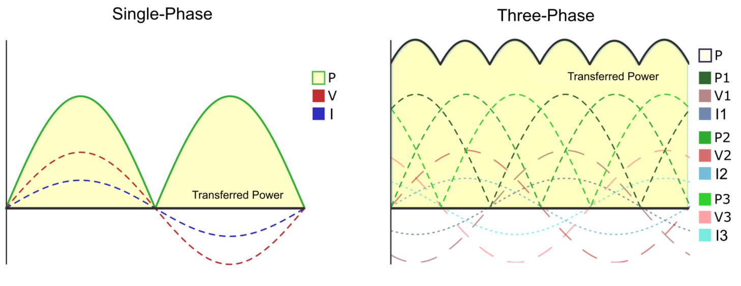
It's not really constant, but it is a lot closer to constant. Here is a graph that shows the comparison:
6_16.png


In a single phase AC source, the left graph shows the voltage (red) and current (blue) waveforms. Multiply these two together (because P = I*V on an instantaneous basis), and you get the green waveform, which is a sine wave with its negative half reflected to the positive.

In three phase, you have the three phase voltages that are each sine waves separated by 120 degree phase shifts, as shown in the right graph. Assuming current is synchronized with voltage, each of the phases will produce a power vs time curve, that follows the three dashed green waveforms. Again, these are sine waves with the negative have reflected to the positive, as a consequence of multiplying two synchronized sine waves of current and voltage together. When you add these up, you get the black path at the top, for the total power vs time graph. There is still a pulsating waveform, but it doesn't dip all the way down to zero, like it does for single phase.
 
I know changing of coils of wire on transformer will change voltage but how do you change * on coils
I dont built transformer, motor or gen bu I wonder how that works.
63dd52c8bd8639aa2810cec0567c0f25.jpg


Great picture
Could someone explain how single transfer 3 PH and single transformer 1PH can have ph shift 120* how it looks physical

Another question to make stuff more complicated what adding capacitor to single PH do?
I am having a hard time understanding exactly what your question is. Are you talking about the phase shift that results from certain transformer configurations, such as a Delta -> wye? Or are you talking about the 120 degree difference between phases on a 3-phase system?
 

Carultch

Senior Member
Location
Massachusetts
So once power is generated 120* it always is 120* ?

If all loads had unity power factor, and there were no non-resistive elements to the transmission and distribution system, the answer would be yes. What that means, is that voltage and current are synchronized, with no phase shift between them. This happens in pure resistive loads.

Where 180 degrees in residential 120/240V grids comes from, is that the transformer primay is connected to just one phase of the 3-phase distribution grid. The transformer secondary is then center-tapped, with the center-tap we call the neutral, that gets bonded to ground. The two waveforms on the remaining wires from the transformer, are equal and opposite in voltage, relative to the neutral. This is mathematically equivalent to two waveforms that are shifted by 180 degrees from one another, but it is produced by negating a waveform, instead of picking up a generator output on a different location on the machinery rotation (as the 3-phase is originally generated).

Given that there are capacitive and inductive loads, there will inevitably be phase shifts between voltage and current, and phase shifts from the original source. This will also cause the voltage to shift in phase, due to the Ohmic voltage drops not being synchronized with the original voltage waveform, as a result of current is shifted in phase. The most that these circuit elements can shift in phase, is 90 degrees. A pure capacitor causes current to come 90 degrees before voltage, and a pure inductor causes current to come 90 degrees after voltage. A typical load's non-unity power factor is around 80%, which means a phase shift of around 36 degrees, with a direction that depends on what kind of load it is. A motor load would cause current to lag, while a DC power supply load would cause current to lead.

The grid is designed to compensate for this issue with power factor correction banks, that work to bring it back to unity power factor as seen by the generating stations. Some loads are also built with their own power factor correction, which is a component of the opposite kind of power factor issue, as the load itself has. Like a motor load with a capacitor in parallel.
 

Hv&Lv

Senior Member
Location
-
Occupation
Engineer/Technician
I don't see why.
Single phase is just single phase.
Beacause apparently the OP doesn’t have a great grasp or electrical theory.
its not as easy as you think to fully explain.
saying “Single phase is just single phase“ doesn’t makes sense to those that don’t understand it. You explained nothing with that statement.

;)
 
Status
Not open for further replies.
Top