HRG system + separately derived system + L-N loads

MechEdetour

Member
Location
NY, USA
This might be a silly question, and I think I know what I am talking about but...

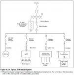
In a 480V high resistance grounded system, L-N loads are not allowed per NEC 250.36. If there are neutral loads to be serviced, a separately derived system can be installed (lets say a 480/277 transformer for lighting loads). The 480/277 system will be solidly grounded, and therefore OCPDs will trip in the event of a L-G fault. Upstream of the 480/277 system will still be high resistance grounded and therefore will only alarm on the first L-G fault.

An image taken from an Eaton application guide to convey a system like I am trying to describe:
hrg-system-jpg.2572491

I think it's my understanding of transformers that is lacking... With the 480/277 transformer being a solidly grounded separately derived system, it allows high levels of fault current to flow to trip OCPDs. But for both HRG and solidly grounded systems the requirements for equipment grounding conductors (EGCs) are more or less the same, the EGCs on the secondary side of the 480/277 transformer would still have continuity with the primary side, and therefore the HRG system as well.

So with all that being said, what is the "source" for fault current to return to if I have a fault on the 480/277 side? Or maybe in other words, how can I have high levels of fault current on the 480/277 side if further upstream (closer to the "source") I still have a neutral grounding resistor that limits my fault current to 5A?

I feel like it's alphabet soup with what I am trying to convey, but it's the best I can do for now.
 

Attachments

  • HRG system.JPG
    HRG system.JPG
    45.1 KB · Views: 49

jim dungar

Moderator
Staff member
Location
Wisconsin
Occupation
PE (Retired) - Power Systems
Separatly derived systems have no interaction between their primary sources and secondary faults. Faults originating on the 480Y/277V secondary must return to that source, even though they may flow over multiple paths.

This is no different than how a fault on the secondary of a 480-208Y/120V transformer secondary does not affect its primary side 480Y/277V ground sensing system.
 

Elect117

Senior Member
Location
California
Occupation
Engineer E.E. P.E.
A transformer is separately derived. Meaning that your ground fault return path is to that transformer and not to the service. This is why transformers are grounded and bonded so similarly to services.

A transformer is isolated/insulated magnetic cores that have a voltage and current relationship. The reason you bring a equipment grounding conductor to the transformer is so that if a fault appears on the primary side the fault can clear. Or if a fault occurs inside the transformer. Or if you overload your primary conductor.

I know I am using terms like high side and low side, but just know that your use case, the high side is the ungrounded / high resistance grounded 480V and the low side would be the 277/480V.

An ungrounded system, with regards to a service, is primarily used to avoid the tripping of the main. This was used (and sometimes still is) on services like manufacturing where the processes would cost a lot just to trip offline on a ground fault. Or in emergency systems like hospitals, police stations, and fire stations.

The ungrounded system has no reference to ground. So the NEC requires, in the cases where it is acceptable to install them, a method of creating one so that personnel can monitor ground faults. A common practice is a high resistance ground or grounding lights. The first ground fault would would show on the grounding lights and then you can schedule maintenance to diagnosis it. It would not trip any thing offline. It would change the potential faulted system to the same potential.

The issue is when you get a second ground fault or a restriking fault on a wye ungrounded system. That's when things start to blow up.
 

ron

Senior Member
Don't believe that electricity wants to flow to ground through the path of least resistance.

It wants to flow to its source's neutral via all available paths relative to their impedance.

The SDS XFMR will allow fault current coming from the XFMR secondary to make its way back to its neutral (X0) via all ground paths and the N-G bond at the SDS to complete the circuit.
 

MechEdetour

Member
Location
NY, USA
Separatly derived systems have no interaction between their primary sources and secondary faults. Faults originating on the 480Y/277V secondary must return to that source, even though they may flow over multiple paths.

This is no different than how a fault on the secondary of a 480-208Y/120V transformer secondary does not affect its primary side 480Y/277V ground sensing system.

So would the EGCs on the primary side not see an increase in current too? I think I can accept the fact that it is separately derived and the fault would clear on the secondary side, but if current flows in all paths, wouldn't some of it still return to another source upstream as well? I know it almost sounds stupid to say it this way, but distribution systems are just a bunch of "nested" transformers with lower voltages, different voltage systems, etc.

Like if I have a 100kVA HV transformer with a 480V secondary feeding a bunch of loads and a 480/277 transformer. And let's say that further downstream, the 480/277 transformer is feeding a 480-208/120 transformer. Would some of the fault current on the 208/120 secondary make it back to the "other sources"? Other sources being the 480/277 transformer and HV/480 transformers...

A transformer is separately derived. Meaning that your ground fault return path is to that transformer and not to the service. This is why transformers are grounded and bonded so similarly to services.

A transformer is isolated/insulated magnetic cores that have a voltage and current relationship. The reason you bring a equipment grounding conductor to the transformer is so that if a fault appears on the primary side the fault can clear. Or if a fault occurs inside the transformer. Or if you overload your primary conductor.

I know I am using terms like high side and low side, but just know that your use case, the high side is the ungrounded / high resistance grounded 480V and the low side would be the 277/480V.

An ungrounded system, with regards to a service, is primarily used to avoid the tripping of the main. This was used (and sometimes still is) on services like manufacturing where the processes would cost a lot just to trip offline on a ground fault. Or in emergency systems like hospitals, police stations, and fire stations.

The ungrounded system has no reference to ground. So the NEC requires, in the cases where it is acceptable to install them, a method of creating one so that personnel can monitor ground faults. A common practice is a high resistance ground or grounding lights. The first ground fault would would show on the grounding lights and then you can schedule maintenance to diagnosis it. It would not trip any thing offline. It would change the potential faulted system to the same potential.

The issue is when you get a second ground fault or a restriking fault on a wye ungrounded system. That's when things start to blow up.

I have a pretty solid grasp on HRGs and the hazards with a second fault, etc. It's really when servicing L-N loads comes into play that my head starts spinning a little bit. I guess I just have a hard time grasping the presence of full fault current on the secondary of a separately derived system with none of that fault current flowing back to the source of the HRG system and therefore through the grounding resistor (even if it is just 5A due to the limiting nature of the resistor).

One other bit I might add. HRGs typically have a time delay when sensing ground faults. It can be 1s, or 5s. It's configurable. Now downstream of the separately derived system the fault current would only be present for a fraction of that time since the OCPD would trip instantly... The HRG would not even react if the current did make it's way to the resistor. But it still begs the question for me, is that fault current of 5A still present for that "instant" duration the fault is present on the separately derived system? Clear as mud?
 

MechEdetour

Member
Location
NY, USA
Don't believe that electricity wants to flow to ground through the path of least resistance.

It wants to flow to its source's neutral via all available paths relative to their impedance.

The SDS XFMR will allow fault current coming from the XFMR secondary to make its way back to its neutral (X0) via all ground paths and the N-G bond at the SDS to complete the circuit.

Ok, I think I'm picking up what you're putting down. And maybe this thought ties together the comments made previously.

The "fault current circuit" is completed at the secondary of a SDS, and there is no case where that fault current would flow into the primary and therefore to a source further upstream. Is this a valid statement? The circuit is complete at the secondary and that is the science. Yes?
 

MechEdetour

Member
Location
NY, USA
Ok so just read the topic pinned at the top of this forum and it answers my question. I think I'll have to read it a few more times for it to really sink in, but I think I can accept that the fault current on the secondary side of a SDS will have no bearing on the primary side (the HRG side).

I'm just going to say it's science, that's how transformers work, and leave it at that. SDS for L-N has no impact on the HRG system upstream.


Any current from a ground fault on the secondary side will only attempt to flow toward a point with a potential difference, which would be the grounded neutral conductor, and no farther. The transformer isolates the secondary from the rest of the world.

The only time current in the secondary system might attempt to flow farher upstream, towards the sub-station supplying the primary system, is in the case of a primary-to-secondary fault within or outside the transformer enclosure.

So, that one conductor of any system is grounded has no effect on the normal flow of current. In a manner of speaking, it makes an accidental contact with a hot wire more dangerous, but it also limits the secondary voltage in case of a primary-to-secondary fault.
 

Elect117

Senior Member
Location
California
Occupation
Engineer E.E. P.E.
Ok, I think I'm picking up what you're putting down. And maybe this thought ties together the comments made previously.

The "fault current circuit" is completed at the secondary of a SDS, and there is no case where that fault current would flow into the primary and therefore to a source further upstream. Is this a valid statement? The circuit is complete at the secondary and that is the science. Yes?

Yes. In a ideal system, the secondary will see the increase in current and open on a ground fault.

In a non-ideal system, there is going to be a reaction on the primary side that results in a slight increase in current. It just is not high enough or fast enough to protect the transformer. Especially where line to neutral loads are concerned.

1720798957336.png

Maybe this image might help?
 

winnie

Senior Member
Location
Springfield, MA, USA
Occupation
Electric motor research
Here is another way of thinking about this:

1) Ignore the HRG system. Imagine that the 480V:480/277V transformer is replaced with a stand alone generator with no electrical connection at all to the HRG system, with the exception that the generator is properly grounded, and thus connected to any grounded/bonded metal. Where does fault current flow? It flows though any bonded metal back to the generator via the neutral to ground bond.

In the event of a fault, the generator produces more output, and the engine has to supply more mechanical power to support the increased electrical power.

2) Now replace the engine of the generator with a motor. This motor is supplied by the HRG system. The result of a fault remains exactly the same as in the generator case; fault current flows back to the generator via the generator's neutral to ground bond. The increased electrical load on the generator means increased mechanical load, and the motor must consume more power from the HRG system to supply this increased mechanical power. Fault current flows on the generator side of things; increased load current (not fault current) flows on the HRG side of things.

3) Now replace the motor/generator system with the primary and secondary of the transformer. The electrical connectivity remains unchanged; only in the case of a transformer you replace the shaft and two rotors with the alternating magnetic flux flowing in the core of the transformer. In the event of a fault on the 480/277V side of the transformer, fault current flows back to the 480/277V secondary via its neutral to ground bond. What flows on the HRG side of things is increased load current.

-Jonathan
 

MechEdetour

Member
Location
NY, USA
Thanks folks. I'll sleep good tonight. I was a part of a discussion the other day where there was concern about servicing L-N loads in an HRG system and there was all this talk about it. I knew that L-N loads were not allowed per the NEC in a high resistance grounded system, but this little bit of missing knowledge bothered me enough not to bring it up. Could have ended the discussion right there.

Next time I'll be able to fire on all cylinders.

Yes. In a ideal system, the secondary will see the increase in current and open on a ground fault.

In a non-ideal system, there is going to be a reaction on the primary side that results in a slight increase in current. It just is not high enough or fast enough to protect the transformer. Especially where line to neutral loads are concerned.

View attachment 2572493

Maybe this image might help?

I already got the answer I was looking for, but the info you shared got me thinking about one other thing. Regarding the comment I highlighted, is this why having secondary protection is beneficial? I understand primary protection is always required and secondary is optional (depending on the size of OCPD, amperage, etc. in 450.3).

Maybe that's why the NEC allows upsizing of primary protection when secondary protection is included since the secondary would protect the transformer before the primary? If I'm opening a rat's nest we can just leave this thread as is... I don't want to convolute protection of secondary conductors that would carry the fault current and protection of the secondary of the transformer.
 

Elect117

Senior Member
Location
California
Occupation
Engineer E.E. P.E.
I already got the answer I was looking for, but the info you shared got me thinking about one other thing. Regarding the comment I highlighted, is this why having secondary protection is beneficial? I understand primary protection is always required and secondary is optional (depending on the size of OCPD, amperage, etc. in 450.3).

Maybe that's why the NEC allows upsizing of primary protection when secondary protection is included since the secondary would protect the transformer before the primary? If I'm opening a rat's nest we can just leave this thread as is... I don't want to convolute protection of secondary conductors that would carry the fault current and protection of the secondary of the transformer.

Without getting into the protection of the conductors on the secondary (or primary side), basically yes. In most 3ph applications, it is required in both the primary and secondary to protect the conductors from overcurrent (but mainly overloading).

It should always exist on the primary side.

Most transformers can handle the overload heating effects until the primary operates. But depending on the wiring (delta-wye, delta-delta, etc.) a fault on the secondary side can destroy the windings before the primary side trips.

It is kind of in the weeds of things. Part 1 is protection of the conductors and part 2 would protection of the transformer. By sizing the overcurrent (ground fault AND overload) protection to the combined applications in 450.3 and 240.21 you will be okay. Where 450.3 protects the equipment, the transformer, and 240.21 protects the wire.
 

wwhitney

Senior Member
Location
Berkeley, CA
Occupation
Retired
The "fault current circuit" is completed at the secondary of a SDS
Yes. If you like, a voltage is an impetus to drive current from point A to point B. And the secondary of a transformer acts as a voltage source--all the current that comes out one wire is driven to return to one of the other wires, and nowhere else. But the current will take all available paths to get back to one of the other wires.

and there is no case where that fault current would flow into the primary and therefore to a source further upstream
No case where it would flow into the primary and then end there, as it need to get back to the voltage source, the secondary. But if there is another path that involves the EGC on the primary side or primary side conductors that will still allow current back to the secondary, it will take that path, too. Such as if the secondary EGC system gets reconnected to the primary EGC system somewhere in addition to at the transformer, then a secondary ground fault would take both paths, through the secondary EGC system and through the primary EGC system.

Cheers, Wayne
 
Top