Incorrect existing feeder size?

Status
Not open for further replies.

Jon456

Senior Member
Location
Colorado
In a commercial building, there is an existing 208V 3-phase 100A fused disconnect (Sylvania GTE RHD323SN) feeding a 225A panelboard (Sylvania GTE ). I'll be replacing the existing panelboard with a Schneider Electric NQ442L2C.

The existing feeders are 1 AWG THW aluminum conductors (current carrying & grounded). However, I can't find any markings on the disconnect or the existing panelboard to indicate that the terminals are rated at 75°C. By my understanding of NEC 110.14(C)(1)(a), if the equipment is not listed and identified for 75°C terminations, then you're required to size the feeders using the 60°C column in Table 310.15(B)(16).

So it seems to me that whoever designed and installed the existing feeders undersized them. Instead of 1 AWG aluminum, they should have been 1/0 aluminum (or 1 AWG copper). Am I correct?
 
I have seen one 60 degree rated terminal in my 40 years, it was on a dryer plug in my house when I moved in. How old is the fused disconnect?
 
I think you're over-thinking it, but if you're correct, can you just convert to compliant wire ends?
 
I'll be honest.

I've installed A LOT of wire and equipment over the years and come into contact with much more, obviously.

I've always sized using the 75 degree column, unless I'm dealing with Romex/UF, etc.

I've also never seen the 15 degree temp difference cause an issue either.

I'm not disagreeing with the code aspect of it, I've just never seen anyone enforce or even look into that side of it.
 
I think you're over-thinking it, but if you're correct, can you just convert to compliant wire ends?
My understanding of the code is that, not just the lugs themselves must be rated at 75°C, but the assembled system (the disconnect or panelboard) must be rated for 75°C. Because it is the combination of the lugs and the connected bus bars that determine the ability for the terminals to conduct heat away from the wire.
 
Frankly, it would be great if I could just assume that the disconnect is rated at 75°C. Unfortunately, that disconnect is pretty old and I haven't been able to find any datasheet for it online. I'll try calling Sylvania tomorrow, but they have since been acquired by Osram, so I suspect it will be a longshot getting a definitive answer on this part.

I know that the new NQ442L2C panelboard is listed and labeled for 75°C terminations. I will be replacing the aluminum feeders and would love to be able to use #3 copper instead of #1 copper.
 
Can't you put terminations (I forgot the right terminology) on the existing conductors that are compatible with the existing terminals? I remember them being crimps with short solid or stranded copper wire leads sticking out. Sometimes used as reducers.
 
The existing feeders are 1 AWG THW aluminum conductors
My theory would be that the THW is the clarified labeling your questioning, which only does appear within the 75 C category, as noted on 310.4 (A)
#1 Aluminum 100A
 
Because it is the combination of the lugs and the connected bus bars that determine the ability for the terminals to conduct heat away from the wire.
Again my theory on this note would be chances are that manufacturers probably rate the lugs, bussing etc on the highest heat anticipated for the voltage and amperage to be utilized that way regardless of the wire type the customer uses they're equipment will accommodate the wiring properties the installer decides to use. It would be kind of reckless for a panel or disconnect manufacturer to design a product that limits the use based on temperature ratings of their connection points, good question though for the manufacturer.
 
I think you're over-thinking it, but if you're correct, can you just convert to compliant wire ends?

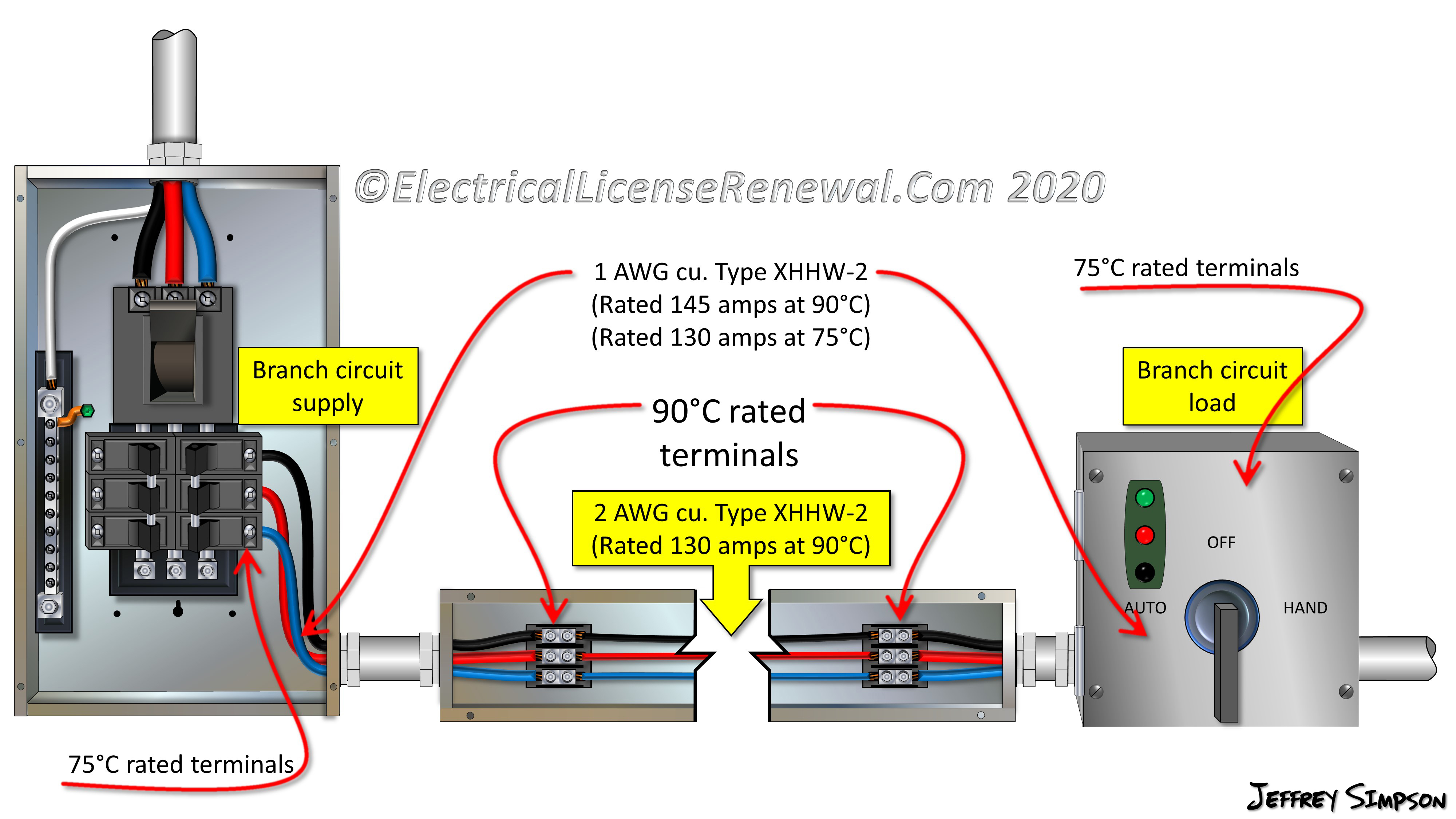
You would need to do your splicing in an external enclosure, to be able to take credit for such solution. Swapping out existing terminals inside the unit would not be enough. The equipment as a listed assembly, would have to be listed for the sizing column you intend to use for termination ampacities, and if not, it would follow the default ratings prescribed in 110.14(C).
 
So it seems to me that whoever designed and installed the existing feeders undersized them. Instead of 1 AWG aluminum, they should have been 1/0 aluminum (or 1 AWG copper). Am I correct?

There is some overlap in the NEC's OR statements, that create an ambiguous gray area, and the NEC is not specific as to how to resolve it. I've sketched a visual to show the issue. Take a closer look at the exact conditions of NEC110.14(C)(1)(a) and NEC 110.14(C)(1)(b). The two sections not only draw the line for whether amp rating (X) is X≤100A vs X>100A. But the two sections also draw a second line for terminal capacity (Y), Y≤#1 vs Y>#1. Examples 3 and 4 show equipment between these two lines, where the rules in parts (a) and (b) contradict each other. Your equipment would be example 3, as would most 100A equipment I've seen in practice. Example 4 is so rare, I don't think it has ever existed. More often than not, equipment is rated for 75C due to most product listings overriding this rule anyway.

1588211562739.png
 
Last edited:
You would need to do your splicing in an external enclosure, to be able to take credit for such solution. Swapping out existing terminals inside the unit would not be enough. The equipment as a listed assembly, would have to be listed for the sizing column you intend to use for termination ampacities, and if not, it would follow the default ratings prescribed in 110.14(C).
I mean the tips you crimp onto the conductors, not swapping out the switch's lugs.

I didn't know the run conductors can't enter the enclosure. It may still be cheaper than replacing the conductors.
 
I mean the tips you crimp onto the conductors, not swapping out the switch's lugs.

I didn't know the run conductors can't enter the enclosure. It may still be cheaper than replacing the conductors.

That's what I've seen in diagrams that show how to take credit for the 90C rating of a conductor, given 75C equipment on both ends. I would assume the same logic applies, when dealing with 60C rated equipment.

qid818.jpg
 
Your equipment would be example 3, as would most 100A equipment I've seen in practice.

View attachment 2552214
Thank you for this detailed explanation. You're correct about the disconnect: the nameplate on the cover lists 100A; the terminals installed are stamped "100Amp 2/0-14".

I have the new NQ442L2C panel and it has a label affixed to it that specifies that it's rated for 75°C and 90°C conductors. So that end of the feeders is no problem.

More often than not, equipment is rated for 75C due to most product listings overriding this rule anyway.
Unfortunately, the old Sylvania GTE has no such label anywhere on it. Nevertheless, I'm going with the 75°C rating. The building in which this was installed was constructed in the 1980's so it's not that old.

I have to extend the feeder conduit a bit for the new panel so I thought I would have to replace the feeders, which enter the panel from the bottom. But the old panel has the main lugs at the top, while the NQ442L2C can be oriented with the main lugs at the bottom. So there should be more than enough excess length in the existing aluminum feeders that I won't have to replace them.
 
Status
Not open for further replies.
Top