PhilBob
Member
- Location
- Philippines
- Occupation
- Electrical & Instrumentation technician
Hi,
I'd like to share an issue that we're currently resolving, and I'd greatly appreciate your input on potential causes and solutions.
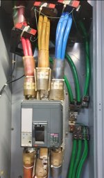
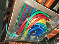
Our team is relatively new to electrical thermography, and we've recently come across an anomaly at the substation where one of the conduits carrying a supply line for the feeder exhibits a high temperature, approximately 70°C, while the other conduits for Phase B and C maintain a normal ambient temperature.
Each conduit contains three wires and one ground wire, all with a size of 200mm².
Additional details:
• No heating or anomalies were detected on the load side. The issues appear to be concentrated upstream.
• No observed ground faults on accessible sections of the line side.
Your insights would be greatly appreciated.
 we.tl
we.tl
I'd like to share an issue that we're currently resolving, and I'd greatly appreciate your input on potential causes and solutions.
Our team is relatively new to electrical thermography, and we've recently come across an anomaly at the substation where one of the conduits carrying a supply line for the feeder exhibits a high temperature, approximately 70°C, while the other conduits for Phase B and C maintain a normal ambient temperature.
Each conduit contains three wires and one ground wire, all with a size of 200mm².
Additional details:
• No heating or anomalies were detected on the load side. The issues appear to be concentrated upstream.
• No observed ground faults on accessible sections of the line side.
Your insights would be greatly appreciated.
WeTransfer | Send Large Files Fast
The simple, quick and secure way to send your files around the world without an account. Share your files, photos, and videos today for free.