Interconnecting Utility and Solar Power Queries

Status
Not open for further replies.

Junior_EE

Member
Location
New York City
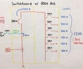
We are designing a system for a new building that parallels utility power and 572Amps-worth of rooftop solar panels@ 480V on a switchboard with a 2500Amp bus. Utility connection and PV connection are made at opposite ends of the switchboard bus. A couple of questions have come out of this:

1.) Per NEC 705.12(B)(2)(b), do I confirm bus size by calculating (which is the correct method?)
a.) 572Amps * 125% + 800Amps < 2500Amp * 120% bus? OR
b.) 572Amps * 125% + 2500Amps < 2500Amp * 120% bus?

2.) Because I potentially have 2500Amps of power from the utility and 572Amps from the solar panels, does this mean I have a building power budget of 2500Amps + 572Amps = 3072Amps?

3.) If I have the budget in #2 above, does this mean the bus needs to have a minimum capacity of 3072Amps instead of 2500Amps?

Thanks for your help!

1626984773169.png
 

don_resqcapt19

Moderator
Staff member
Location
Illinois
Occupation
retired electrician
The drawing shows 2500 amp bus. 705.12(B)(3)(2) applies and the maximum permitted rating of the solar input would be 500 amps.
 

Junior_EE

Member
Location
New York City
The drawing shows 2500 amp bus. 705.12(B)(3)(2) applies and the maximum permitted rating of the solar input would be 500 amps.
Can you clarify which version of NEC you are mentioning here? We are using NEC 2017 for this project and the section of code you mention does not appear to exist.

Anyone else have any insight into this issue, as well as into #2 and #3?
 
Last edited:

Carultch

Senior Member
Location
Massachusetts
Can you clarify which version of NEC you are mentioning here? We are using NEC 2017 for this project and the section of code you mention does not appear to exist.

Anyone else have any insight into this issue, as well as into #2 and #3?

This is informally known as "the 120% rule". The substance of the rule has been the same since NEC2014, but the reference of the rule has moved around, due to this section being reorganized. Prior to 2014, it was PV breaker + Main breaker <= 120% busbar. NEC2014 and later, they replaced PV breaker with the calculation that sizes the breaker, prior to rounding up to the size you are actually using.

In your example, I'm going to set B for busbar rating as a variable. It was given at 2500A, but 2500A is insufficient.

In 2011 and prior, the correct equation would've been 800A + 2500A <= 120% * B. This would calculate a minimum of B= 2750A.
In 2014 and later, the correct equation now becomes (125% * 572A) + 2500A <= 120% * B. This would calculate minimum B = 2670A. As you an see, 125%*572A is how we size the 800A breaker, with rounding up to a standard size being the next step. Except instead of using the value that rounds to 800A, we use the output of the calculation that sized the 800A breaker, prior to rounding to 800A

See the graphics from this source, that give you a better visual understanding of the equations the code gives:

Option B is the "120% rule", that allows you to take credit for feeding at the opposite end of the bus from the main supply. You get to have 20% of the busbar rating as headroom to interconnect, assuming you have a main that matches your busbar.
1627436346977.png

The reason we get to do this, is that current in opposite directions is subtractive, rather than additive. At no point along the busbar, will current ever exceed 2500A or 800A in your example. The 800A feeds the nearest loads until it diminishes to zero. Then the main supply fills in the rest. The reason why it isn't as permissible as a 200% rule, as Kirchhoff's current law alone would seemingly allow, is mutual heating among the breakers. 120% is an industry compromise, that sets the limit for how much you can take credit for feeding the busbar from opposite ends, in order to mitigate the risk of overheating the branch breakers. If you want to increase the PV interconnection beyond 500A of OCPD (i.e. 400A of total inverter current), you either need to reduce your main breaker, or increase your busbar.

You can supply loads from both sources simultaneously, and in concept, it could draw the total from the main supply, plus the PV production. However, you still have the same load calculation to size the main breaker, as if the solar weren't there. You don't want to trip your main breaker on a plausible amount of building load at the peak demand, just because an inverter isn't working. Reducing the size of your main breaker is one strategy to allow a larger interconnection, but you have a burden of proof if you desire to do so. Either with a load calculation, or with 30 days of interval power data.

Adding the solar will allow the system to draw over 3000A in your example, in the event that you consume more instantaneous power than the load calculation predicted, and it allows you to do so without tripping your main. It will not add up to 3000A at any cross-section of the busbar, because opposite directions of current are not additive. This is an unlikely event, because rules that govern how to size a service/main feeder to a loads panelboard require you to make it an unlikely event.
 
Last edited:

Carultch

Senior Member
Location
Massachusetts
Additional thoughts about load calculations:
Load calculations do not necessarily determine worst case scenario, that you deliberately go out of your way to turn on everything at once. If you did that, you'll trip your main breaker. Instead, load calculations determine how your total load will realistically add up, given statistical models of user behavior for how much of your load is likely to be concurrent. That way, your service size is realistic for what current will most likely flow on the conductors, during the service life.
 

Junior_EE

Member
Location
New York City
This is informally known as "the 120% rule". The substance of the rule has been the same since NEC2014, but the reference of the rule has moved around, due to this section being reorganized. Prior to 2014, it was PV breaker + Main breaker <= 120% busbar. NEC2014 and later, they replaced PV breaker with the calculation that sizes the breaker, prior to rounding up to the size you are actually using.

In your example, I'm going to set B for busbar rating as a variable. It was given at 2500A, but 2500A is insufficient.

In 2011 and prior, the correct equation would've been 800A + 2500A <= 120% * B. This would calculate a minimum of B= 2750A.
In 2014 and later, the correct equation now becomes (125% * 572A) + 2500A <= 120% * B. This would calculate minimum B = 2670A. As you an see, 125%*572A is how we size the 800A breaker, with rounding up to a standard size being the next step. Except instead of using the value that rounds to 800A, we use the output of the calculation that sized the 800A breaker, prior to rounding to 800A

See the graphics from this source, that give you a better visual understanding of the equations the code gives:

Option B is the "120% rule", that allows you to take credit for feeding at the opposite end of the bus from the main supply. You get to have 20% of the busbar rating as headroom to interconnect, assuming you have a main that matches your busbar.
View attachment 2557362

The reason we get to do this, is that current in opposite directions is subtractive, rather than additive. At no point along the busbar, will current ever exceed 2500A or 800A in your example. The 800A feeds the nearest loads until it diminishes to zero. Then the main supply fills in the rest. The reason why it isn't as permissible as a 200% rule, as Kirchhoff's current law alone would seemingly allow, is mutual heating among the breakers. 120% is an industry compromise, that sets the limit for how much you can take credit for feeding the busbar from opposite ends, in order to mitigate the risk of overheating the branch breakers. If you want to increase the PV interconnection beyond 500A of OCPD (i.e. 400A of total inverter current), you either need to reduce your main breaker, or increase your busbar.

You can supply loads from both sources simultaneously, and in concept, it could draw the total from the main supply, plus the PV production. However, you still have the same load calculation to size the main breaker, as if the solar weren't there. You don't want to trip your main breaker on a plausible amount of building load at the peak demand, just because an inverter isn't working. Reducing the size of your main breaker is one strategy to allow a larger interconnection, but you have a burden of proof if you desire to do so. Either with a load calculation, or with 30 days of interval power data.

Adding the solar will allow the system to draw over 3000A in your example, in the event that you consume more instantaneous power than the load calculation predicted, and it allows you to do so without tripping your main. It will not add up to 3000A at any cross-section of the busbar, because opposite directions of current are not additive. This is an unlikely event, because rules that govern how to size a service/main feeder to a loads panelboard require you to make it an unlikely event.
This is a phenomenal response, and it is greatly appreciated. Thank you so much!
 

don_resqcapt19

Moderator
Staff member
Location
Illinois
Occupation
retired electrician
Prior to NEC 2020, the rules discussed by Carultch, I believe, apply to panelboards alone. This changed in NEC 2020, where it applies to any busbar fed from multiple sources.
It applies to switchboards, panelboards, and switchgear going back to at least the 2011 code.
 
It applies to switchboards, panelboards, and switchgear going back to at least the 2011 code.
I don't think so. For example, 2014 705.12(D)(2)(3) reads:

Busbars. one of the methods that follow shall be used to determine the ratings of bus bars in panel boards......

I know there has been a little bit of debate about this, but the language seems very clear to me that that applies only to panel boards, whether they intended it that way or not.
 

don_resqcapt19

Moderator
Staff member
Location
Illinois
Occupation
retired electrician
I don't think so. For example, 2014 705.12(D)(2)(3) reads:

Busbars. one of the methods that follow shall be used to determine the ratings of bus bars in panel boards......

I know there has been a little bit of debate about this, but the language seems very clear to me that that applies only to panel boards, whether they intended it that way or not.
I am looking at the parent text that includes all, but yes, there is debate on this issue.
 
Status
Not open for further replies.
Top