moonshineJ
Member
- Location
- USA
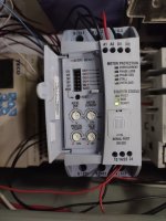
In WEG SSW05 Plus I have R to U about 1 MΩ, S to V about 1 MΩ, T to W less than 1 Ω. When 480 VAC is applied to R, S, T, I immediately have power available at U, V, W even though there is no start signal order. No load connected to the output, by the way.
There is voltage drop of about 25 VAC across R-U and S-V, and almost zero across T-W.
IF I do apply the starting command, I have red LED Phase Loss on, which is understandable, since I have no motor connected.
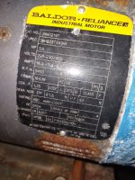
The two identical controllers were installed to control two small (7.5 kW) water pumps (which was strange to begin with to use a softstart for a small size pump motor, which can be cycling on and off frequently). The project was never finished, and different people have been working on it in last 3-4 years.
I took the ohmic readings (no voltage checks!) on the second controller, and they are exactly the same.
It looks like T-W is somehow dead shorted inside, but why it's only between T and W on both controllers?
I saw at least one similar thread on this forum (though a different brand) and several other instances on other websites when electricians run into the same scenario.
Is this softstart busted? There should be no way to read between T and W in de-energized state, not to mention to observe full voltage output on U, V, W without starting command. If the softstart is bad, what potentially could cause such damage? IF IT ISN'T bad, isn't it weird and dangerous that a softstart having no starting command has a full output voltage across it?
There is voltage drop of about 25 VAC across R-U and S-V, and almost zero across T-W.
IF I do apply the starting command, I have red LED Phase Loss on, which is understandable, since I have no motor connected.
The two identical controllers were installed to control two small (7.5 kW) water pumps (which was strange to begin with to use a softstart for a small size pump motor, which can be cycling on and off frequently). The project was never finished, and different people have been working on it in last 3-4 years.
I took the ohmic readings (no voltage checks!) on the second controller, and they are exactly the same.
It looks like T-W is somehow dead shorted inside, but why it's only between T and W on both controllers?
I saw at least one similar thread on this forum (though a different brand) and several other instances on other websites when electricians run into the same scenario.
Is this softstart busted? There should be no way to read between T and W in de-energized state, not to mention to observe full voltage output on U, V, W without starting command. If the softstart is bad, what potentially could cause such damage? IF IT ISN'T bad, isn't it weird and dangerous that a softstart having no starting command has a full output voltage across it?