Isolating Multi-Ratio Current Transformer(s)

Status
Not open for further replies.

Shepherd1

Member
Location
Edmonton
Occupation
Engineer
I could use some input regarding isolating a multi-tap current transformer on-the-run.

We are planning a job to replace a temperature gauge on a 35 / 4.16 kV transformer. As part of the transformer gauge, a heater element is fed from a Multi-Ratio Hot-Spot CT (X1 & X3 in use, X2/X4/X5 Open) internal to the transformer. To replace the gauge, we will need to disconnect the wires feeding the Hot-Spot CT wires to the heater element.

During the pre-job investigation, it was found that the factory had improperly installed the CT secondary wires and heater wires on the same side of the local shorting block, inside the transformer control cabinet.

Under normal circumstances we would jumper all windings to ground via the shorting block and move on with the work. However, due to the wires being installed on the same terminal of the shorting block, we will have to disconnect the X1 & X3 wires, open circuiting a portion of the Hot Spot CT Circuit.

The current plan is to the short X2 and X5 windings to ground at the local shorting block, done to provide a secondary loop for current to flow, and then to open the existing X1 and X3 circuit; avoiding hazardous voltage build-up on the X1 and X3 windings.

The concept that I am having trouble reconciling with is when the X1 wire is lifted on the shorting block, what is inhibiting the CT from building up voltage on the X1/X3 windings after X2 & X5 are shorted to ground?

I have found an old post from 2005 (Differential protection relay CT wiring question | Mike Holt's Forum), where rcwilson, discusses something similar.
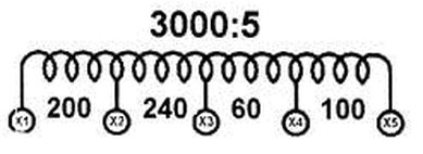


multiratio-drawings.jpg


*Picture for Reference Purposes
 
That's correct, we are looking to isolate the hotspot CT circuit before work.

We have been been in touch with the manufacturer who advised that this gauge replacement can occur while the 35 /4.16 kV transformer is energized.

I am just looking to verify how to safely isolate the mutli-ratio CT, while under load, before work begins.
The point is for the most part you cannot do so. You have to shut the power off to work on the things. This might be inconvenient but there are only a few cases where you're allowed to work on equipment that is energized.
 
210102-1156 EST

Sherpherd1:

I can not understand this thread. You list yourself as an engineer. Thus, you should know how transformers work, including current transformers.

Your circuit diagram does imply that you are actually talking about a current transformer.

A basic rule relative to a magnetic current transformer is that the secondary must always be shorted (low impedance load on the secondary) when current is present thru the primary. Why? Because very large secondary voltages can be created otherwise.

Since you have one continuous secondary winding, according to your drawing, with multiple taps you can short any two separate secondary taps together and achieve the shorted effect. The grounding, earthing, of any one of the secondary taps will hold the secondary near ground potential. In other words no major floating voltage should develop relative to earth.

I don't understand how a current transformer measures a hot spot. The maximum hot spot point in a transformer is determined by the physical design of the transformer. This is a thermal resistance problem.

Potentially a current transformer monitoring the primary current on a power transformer can help detect the presence of shorted turns, primary or secondary, if you have historical data on no load transformer current at various primary voltages, and you know the primary voltage at the time of the current measurement.

A shorted turn or turns will create a hot spot in the region of the short, but I can not know that location by a simple primary current measurement.

.
 
The hotspot CT drives a current into a heater which raises the local temperature in a well containing the temperature sensor so that it matches the same temperature rise that occurs at the hottest part of the windings. In other words, it replicates the temperature that will occur at the hotspot with a given amount of current through the power transformer and primary of the CT. That way the temperature sensor doesn't have to be in the tank near the actual hotspot.

The current plan is to the short X2 and X5 windings to ground at the local shorting block, done to provide a secondary loop for current to flow, and then to open the existing X1 and X3 circuit; avoiding hazardous voltage build-up on the X1 and X3 windings.

The concept that I am having trouble reconciling with is when the X1 wire is lifted on the shorting block, what is inhibiting the CT from building up voltage on the X1/X3 windings after X2 & X5 are shorted to ground?

As gar mentioned, shorting across other taps should be OK, at least as far as preventing damage to the CT from overvoltage.
Now even though it's OK for the CT, there will still be some voltage developed on the disconnected windings and so appropriate PPE and insulated tools would of course be required in making changes. I'd recommend measuring the existing voltages across open windings such as X3 to X5 to see what you're up against before proceeding further.

Assuming you are replacing the heater, can you just cut the existing heater wires with shorting screws in place and then leave the existing heater connections and CT connections to the shorting block intact? Cap off the stubs that are left of the old heater wires. Then connect the new heater wires to the other side of the shorting block. That would avoid having to deal with the CT at all.
 
As long as there is a load or burden on x2 and x5 (or x4), you can lift x1 and x3 and change the wires.

There isn’t a need to short ALL the taps to work on these ( for future reference).

While it’s best to short across the entire coil,(x1-x5), you’ll be ok the way your suggesting.

think of it this way. Your using x1 and x3 now. How much current flows through the wire on x2? what happens if you take it off the shorting block?

Whether it’s landed on the shorting block or hanging in the open, no difference.

We have changed these before on a 115/24.9 transformer, and it was energized. Takes about 30 minutes..
 
Switchgear comes with shorting blocks specifically so that the relays can be disconnected for service and testing. You can’t remove CTs in service except some of the split core types that have an internal resistor.

In most of them the taps are set at the CTs but I’ve also seen arrangements where all the taps are brought out to a terminal block so that changes can be made without opening the power side. Regardless this is easily done by racking breakers out.

We have an unusual arrangement in a motor test stand at work. It has two CTs. One is 200:5 and the other is 2000:5, for accuracy reasons. They share the same inputs and switching is done with mercury relays. Surge arresters are used for “shorting” so that whichever CT is offline is voltage and thus current limited. Bringing this up just to give you ideas how others have solved it.
 
Status
Not open for further replies.
Top