good evening all,
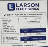
I looking for some guidance pertaining to two isolation transformers a client of mine needed to have installed for some RF equipment. This equipment takes 230 V single phase line and neutral. The building is equipped with 208 3 phase so I took single phase 208 to my primary and expected to have 230 V line to neutral on the secondary. Line to neutral. I got 230 V but neutral to ground. I have 120. So then I thought I could bond neutral ground with a grounding electrode and my equipment, grounding conductors for the circuits. That worked, but then while taking amp readings I found the grounding electrode had 3.5 amps on it.
I had the customer hook up his RF equipment to the set up. I had first and everything worked fine. My worry is if I bond the neutral the secondary current will then get onto the grounding electro conductor, and if something were to come loose, it could become a potential shock hazard. I am wondering why this is happening. Also, my understanding of an isolation transformer is that if you read hot to ground, you should read 0 V. Also, the same with neutral. Also, my worry is there is filters that the power hits before going into an RF chamber. This filter, specifies line and neutral. I am worried if there is voltage on the neutral the filter could eventually fail. I would really appreciate the help.