mbrooke
Batteries Included
- Location
- United States
- Occupation
- Technician
Thought I would ask this here- forgive me if this is outside the scope of the forum by any chance.
Is it typically industry practice, or recommended that motor operated disconnects have interlocking (error) logic or is a switching procedure checklist and strict protocol considered satisfactory?
Second, does an enable switch for the rotary switches controlling the motor operators and breaker sound typical on the mimic board?
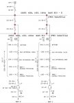
Here is an example:
1. Bay isolator 202-89-L can not be operated unless circuit breaker 202-52-CB is open- this prevents the inadvertent operation where the isolator could break full current and voltage.
2. Bus isolator 202-89-A will only open if 202-89-B is in the closed state, and 202-89-B will only open if 202-89-A is closed assuming breaker 202-52-CB is closed.
3. 202-89-A and 202-89-B can only be closed together (or one opened when both are closed) if the bus coupler is also closed. Ie 89-A OR 89-B can close, but once that happens the other can not close unless 52A is asserted on the coupler breaker. If both are closed neither one can open unless BC is closed.
I know this is showing only one bus type as an exmaple, however my question basically applies to all bus types as it is still relevant IMO.
Finally, is CT over current logic with a pickup/drop out timer helping make the open breaker decision a stable marker? Or 52A contact? Or something more extravagant?
Is it typically industry practice, or recommended that motor operated disconnects have interlocking (error) logic or is a switching procedure checklist and strict protocol considered satisfactory?
Second, does an enable switch for the rotary switches controlling the motor operators and breaker sound typical on the mimic board?
Here is an example:
1. Bay isolator 202-89-L can not be operated unless circuit breaker 202-52-CB is open- this prevents the inadvertent operation where the isolator could break full current and voltage.
2. Bus isolator 202-89-A will only open if 202-89-B is in the closed state, and 202-89-B will only open if 202-89-A is closed assuming breaker 202-52-CB is closed.
3. 202-89-A and 202-89-B can only be closed together (or one opened when both are closed) if the bus coupler is also closed. Ie 89-A OR 89-B can close, but once that happens the other can not close unless 52A is asserted on the coupler breaker. If both are closed neither one can open unless BC is closed.
I know this is showing only one bus type as an exmaple, however my question basically applies to all bus types as it is still relevant IMO.
Finally, is CT over current logic with a pickup/drop out timer helping make the open breaker decision a stable marker? Or 52A contact? Or something more extravagant?