Just need confirmation for Motor feeder protection calculations, please.

Status
Not open for further replies.
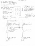
Hi, I have a Lift station with 2, 3hp, 240vac, 3 phase pumps.

I need to replace the 60A Fused, 3-pole, double-throw, safety switch with 6, 60A fuses, which feeds two 20A IT breakers. Each of these breakers feeds a size 0 motor starter with overload protection. I have added a drawing of what I have as an attachment. I just need someone to check my calculations to make sure I am upgrading to code.

Thank You,
Mike
 

Attachments

  • LiftStationCalculations.jpg
    LiftStationCalculations.jpg
    76.2 KB · Views: 0
My math came up with a Feeder SCGF protection of 35 amps. The SCGF on one motor plus the FLA of the 2nd motor 430.62
 
My math came up with a Feeder SCGF protection of 35 amps. The SCGF on one motor plus the FLA of the 2nd motor 430.62

--The 25A ckt. breaker in each leg was chosen because each pump has a FLC of 9.6A. So, 9.6A x 250% (Table 430.52, squirrel cage, Inverse Time Breaker)=24A. Next standard size is 25A Breaker.

--I chose #10 wire, for feeder conductors, instead of the allowable #12 simply for preference.

--I chose 30A Dual Element Fuses for Feeder OCP because my largest breaker is 25A. 25A + 9.6FLC = 34.6A. In order not to exceed this value I chose 30A.
 
Do your math again. I can see what you possibly did, but explain why.


--The 25A ckt. breaker in each leg was chosen because each pump has a FLC of 9.6A. So, 9.6A x 250% (Table 430.52, squirrel cage, Inverse Time Breaker)=24A. Next standard size is 25A Breaker.

--I chose #10 wire, for feeder conductors, instead of the allowable #12 simply for preference.

--I chose 30A Dual Element Fuses for Feeder OCP because my largest breaker is 25A. 25A + 9.6FLC = 34.6A. In order not to exceed this value I chose 30A.
 
If the 30 amp fuses were noted on the diagram originally, I missed it and zeroed in on the 60 amp switch. With 30 amp fuses, I see no problem.
 
Your full load amps is just the sum of the two motors, 19.2A. The 25A is not a load, it’s just the rating of the breakers on the same circuit as each motor.
 
A 30A switch is fine.
Is this a control panel or are the starters each in their own separate enclosures as factory built combo starters? Assuming all separate parts, I would use a stand alone main breaker rated 30A, then feed that to a non-fused manual transfer switch (double throw safety switch). Then feed the two combo starters (through a gutter with a distribution block). Using a fused MTS means having 6 fuses, which means 6 ways of single phasing those motors. The generator likely has its own breaker anyway, and I don’t think you can get a SUSE label on a double throw safety switch (I might be totally wrong on that though).

If this is a control panel, you can’t use IT breakers on your own, they are only legal in factory built and tested/listed assemblies. Those breakers would need to be Thermal-Mag.
 
It looks a little goofy to me but also looks code compliant.

i would get rid of the fuses. If you are going to the trouble of allowing for a generator connection it seems like reliability is important and it is possible the fuses could blow and there be no spares, where with a CB you can just reset it.

I don't think you need to protect the generator line as the genset will have its own protection.
 
A 30A switch is fine.
Is this a control panel or are the starters each in their own separate enclosures as factory built combo starters? Assuming all separate parts, I would use a stand alone main breaker rated 30A, then feed that to a non-fused manual transfer switch (double throw safety switch). Then feed the two combo starters (through a gutter with a distribution block). Using a fused MTS means having 6 fuses, which means 6 ways of single phasing those motors. The generator likely has its own breaker anyway, and I don’t think you can get a SUSE label on a double throw safety switch (I might be totally wrong on that though).

If this is a control panel, you can’t use IT breakers on your own, they are only legal in factory built and tested/listed assemblies. Those breakers would need to be Thermal-Mag.

in a later post the OP stated IT = inverse time, not instantaneous.
 
A 30A switch is fine.
Is this a control panel or are the starters each in their own separate enclosures as factory built combo starters? Assuming all separate parts, I would use a stand alone main breaker rated 30A, then feed that to a non-fused manual transfer switch (double throw safety switch). Then feed the two combo starters (through a gutter with a distribution block). Using a fused MTS means having 6 fuses, which means 6 ways of single phasing those motors. The generator likely has its own breaker anyway, and I don’t think you can get a SUSE label on a double throw safety switch (I might be totally wrong on that though).

If this is a control panel, you can’t use IT breakers on your own, they are only legal in factory built and tested/listed assemblies. Those breakers would need to be Thermal-Mag.


My situation is the latter (it's a control panel with both starters). And as far as the breakers go, I got confused after looking at the Table 430.52 about the IT breakers. I'll go with TM. Thanks.
 
It looks a little goofy to me but also looks code compliant.

i would get rid of the fuses. If you are going to the trouble of allowing for a generator connection it seems like reliability is important and it is possible the fuses could blow and there be no spares, where with a CB you can just reset it.

I don't think you need to protect the generator line as the genset will have its own protection.


Great idea.
 
Status
Not open for further replies.
Top