Legitimate Install, Part....

Status
Not open for further replies.

360Youth

Senior Member
Location
Newport, NC
Sorry I do not have any actual pics, but is this a NEC compliant install?

CTBonding-1.jpg


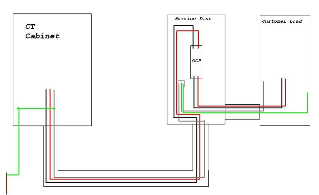
POCO feeds CT. SE conductors feed underground to main disconnect. It is a 3-wire feed from CT to main disconnect and 4-wire from main diconnect to remaining customer load(s). At the CT the cabinet and GEC are bonded to grounded conductor to complete the path.
 
quogueelectric said:
The bonding and grounding should take place at the main disconnect here.

Should the 3-wire feed be 4-wire? I have read opinions that this creates a parallel neutral since they are bonded at the disconnect.
 
360Youth said:
Should the 3-wire feed be 4-wire? I have read opinions that this creates a parallel neutral since they are bonded at the disconnect.
Specifically which wires are you calling the feed and the picture does not show the neutral bonded at the disconnect it shows it bonded at the ct cabinet. Some inspectors have asked me to drive a ground rod at the ct cabinet when my piping system is pvc but I think that it is wrong and I dont want to press thier buttons so I just add a ground rod there to get passed.
 
quogueelectric said:
Specifically which wires are you calling the feed and the picture does not show the neutral bonded at the disconnect it shows it bonded at the ct cabinet. Some inspectors have asked me to drive a ground rod at the ct cabinet when my piping system is pvc but I think that it is wrong and I dont want to press thier buttons so I just add a ground rod there to get passed.

I am calling the supply conductors between CT and Disc the 3-wire feed. (Yes, I know it is not "feeder" :smile: )

The square surrounding the supply grounded, load grounded, and EGC is the bonding point. I forgot to draw the bonding jumper, in this case factory screw.
 
most POCO's don't allow grounding inside their meter or CT

Was their a reson to start a new thread. And a non compliant one at that?
 
360Youth said:
I am calling the supply conductors between CT and Disc the 3-wire feed. (Yes, I know it is not "feeder" :smile: )

The square surrounding the supply grounded, load grounded, and EGC is the bonding point. I forgot to draw the bonding jumper, in this case factory screw.
Then just scoot that ground rod over there and pick up a water main there and call it a day.
 
I say the drawing is perfectly compliant as far as the NEC is concerned. The electrode can attach to the neutral at any point from the point of attachment (i.e., service point) to the main disconnect enclosure.

The POCO may have something to say about the electrode connection, as mentioned above. I wish we could land the electrode in the meter. It's the perfect place: it's already outside and the shortest path.
 
If the CT is at a remote location, as shown,, it really does not change anything unless there is a disco at the remote location. One can argue that a disco is needed out there at the CT since it is a structure. If that is the case then a 4 wire would be needed back to the main disco at the bulding.

Also I believe there would be a ground rod needed at the CT as well as at the main disco.

So I would say the drawing is not compliant since it is missing the ground rod at the main disco
 
LarryFine said:
I say the drawing is perfectly compliant as far as the NEC is concerned. The electrode can attach to the neutral at any point from the point of attachment (i.e., service point) to the main disconnect enclosure.

The POCO may have something to say about the electrode connection, as mentioned above. I wish we could land the electrode in the meter. It's the perfect place: it's already outside and the shortest path.

The CT metering is there at the cabinet so that is where the electrode is. Two ground rods.

Dennis Alwon said:
If the CT is at a remote location, as shown,, it really does not change anything unless there is a disco at the remote location. One can argue that a disco is needed out there at the CT since it is a structure. If that is the case then a 4 wire would be needed back to the main disco at the bulding.

Also I believe there would be a ground rod needed at the CT as well as at the main disco.

So I would say the drawing is not compliant since it is missing the ground rod at the main disco

The CT is mounted on the house feeds under paved garage and to main disconnect in mechanical room, the first point of entry to the home. There are 2 ground rods at the CT. The question is: Is the grounding electodes tied to the system grounded at the CT a sufficient fault path to ground. Everything I read says it is, but I cannot settle it in my head. They would be tied together with listed lug at the CT to the POCO's service lateral connections.
 
Status
Not open for further replies.
Top