Light Dimmer

Status
Not open for further replies.

mull982

Senior Member
I was having a conversation with a co-worker trying to explain how a light dimmer switch works.

I explained that the light dimmer was like a potentiometer that varied that was a variable resistor. When increasing the resistance on this resistor this would limit the current flow through the light circuit and therfore cause the light to dim.

The reason the light dims is becasue of the fact the the amount of light is equal to the electrical power in the light represented by I^2R. So by increasing the resistance via the dimmer the current will decrease and thus decrease the power in the light and causing it to dim.

Is this a correct explanation?
 
I was having a conversation with a co-worker trying to explain how a light dimmer switch works.

I explained that the light dimmer was like a potentiometer that varied that was a variable resistor. When increasing the resistance on this resistor this would limit the current flow through the light circuit and therfore cause the light to dim.

The simplest explanation, in my view, is that it works by reducing the voltage fed to the light.
 
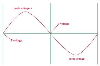
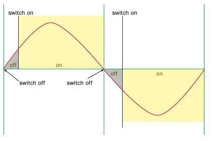
Most dimmers work by 'chopping off' portions of the sine wave.

Normal sine wave:

Dimmer1.jpg


Dimmed sine wave:

Dimmer2.jpg


Humming is produced by the physical movement of the filament as the current is cycled on and off. Most noticable at between 40-60% of the dimmers' range, it can be recuded by either using a better-grade dimmer, or higher-quality bulbs (which usually have more filament supports built into them).

New non-chopping dimmers are on the market, and actually provide a complete sine wave, but a lower voltage.
 
Last edited:
In years gone by dimmers did consist of a large variable resistance wired in series with the lamp.
These produced very considerable heat, and were not really suitable for domestic use.

As pointed out above, almost all modern dimmers use a semi-conductor device to only supply power to the lamp for a variable part of each cycle of the mains frequency.
This has the advantage that the only heat produced is from the losses in the electronics, often about 1% of the load.

Another way of dimming a lamp is to use a variable ratio transformer, often called a variac, though in fact that is a trade name.
The cost and bulk of a variable transformer is much greater than a semi conductor dimmer, therefore these are only used in special cases.
 
Variable resistor dimmer are long gone. For one they didn't save energy like newer wave altering dimmers do.
 
As pointed out above, almost all modern dimmers use a semi-conductor device to only supply power to the lamp for a variable part of each cycle of the mains frequency.
This has the advantage that the only heat produced is from the losses in the electronics, often about 1% of the load.
It's true that the losses are small compared to input power. But incandescents are pretty inefficient anyway - you might convert less than 5%of input power to light at full voltage and much less at reduced voltage.
Phase-controlled dimmers have another undesirable side effect - harmonics.
In particular, the third can be a big problem resulting in overloaded neutrals.
I have a little bit of history on this.
But that's a different story.
 
Most dimmers work by 'chopping off' portions of the sine wave.

Normal sine wave:

Dimmer1.jpg


Dimmed sine wave:

Dimmer2.jpg


Humming is produced by the physical movement of the filament as the current is cycled on and off. Most noticable at between 40-60% of the dimmers' range, it can be recuded by either using a better-grade dimmer, or higher-quality bulbs (which usually have more filament supports built into them).

New non-chopping dimmers are on the market, and actually provide a complete sine wave, but a lower voltage.

So by switching voltage on and off what effect does this have on the load? Does the load see a reduced voltage or a reduced power? I wouldn't think that it would be seeing a reduced voltage because even with switching there are still some points where voltage will be at its peak.

I variable resistors were still used was my explanation correct about limiting the current, or is it more the effect of limiting the voltage at the light which will in turn cause less of a current draw?


The RMS voltage will be reduced.
 
The RMS voltage will be reduced.

O.K. I see how this would effect the RMS voltage and cause a reduced voltage to be seen at the light.

With this reduced voltage at the light, this would mean that there would be reduced current at the light as well. What has the overall effect of dimming the light, is it the lack of voltage or the lack of current or combination of both resulting in a lack of power seen by the light.
 
The RMS voltage will be reduced.

When you think in terms of energy, the light is the product of electrical energy conversion into light energy. Looking at the sinewave diagram the 'yellow' area is convered and the grayed area will be missing from the 'full-on' position. (Of course you also have to add the current into the picture, but that will be in phase with the voltage and chopped likewise, the energy is of course I*U.
 
O.K. I see how this would effect the RMS voltage and cause a reduced voltage to be seen at the light.

With this reduced voltage at the light, this would mean that there would be reduced current at the light as well. What has the overall effect of dimming the light, is it the lack of voltage or the lack of current or combination of both resulting in a lack of power seen by the light.

With any dimming method, both the voltage and the current are reduced. Therefore power is reduced.

A rheostat adds resistance to the circuit, and the waveform is maintained, but it wastes a lot of power.

A Variac or Powerstat, reduces the voltage through transformer action, and the waveform is maintained. There is minimal power loss. I think these may still be used in stage lighting.

Triacs reduce the voltage though duty cycle control, and the waveform is distorted. This method tends to generate RF noise which must be filtered. A bit of math is required to compute the RMS voltages and currents with this method. Power loss is minimal.
 
Most dimmers work by 'chopping off' portions of the sine wave.

Normal sine wave:

Dimmer1.jpg


Dimmed sine wave:

Dimmer2.jpg


Humming is produced by the physical movement of the filament as the current is cycled on and off. Most noticable at between 40-60% of the dimmers' range, it can be recuded by either using a better-grade dimmer, or higher-quality bulbs (which usually have more filament supports built into them).

New non-chopping dimmers are on the market, and actually provide a complete sine wave, but a lower voltage.

Hey Sparky, yur impress'n me !! that's pretty good
 
The sine wave 480 posted is typical of low cost dimmers we all use for incandescent lamps. But that type will overheat transformers used for low voltage lighting.

If we look at the sine wave for low voltage dimmers it would be opposite, instead of the abrupt jump in voltage on the leading edge it the leading edge would ramp up smoothly then fall off abruptly on the trailing edge.

I also believe there is a third type that leaves the smooth ramps on each edge but flattens the top of the sine wave.
 
Status
Not open for further replies.
Top