mgookin
Senior Member
- Location
- Fort Myers, FL
We manufacture outdoor light controls. We use the industry standard ANSI C136.10 twist-lock interface. Our product is listed 120-277VAC 1800VA. We have installations throughout North America, Europe and Australia without a single failure, except this one contactor which eats up our product, and it's a different issue every time.
So we went outand did some research. Here are our findings:
The lights are 480VAC single phase.
The contactor is a Square D series 8903 type SQH63 plus twist lock receptacle and lightning arrestor (form G101Y1532).
Contactor rating = 100A.
Load = 53 *400W = 21.2kVA /480 = 44A.
The contactor coil is 240VAC single phase.
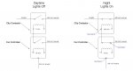
Measuring from neutral to line at the twist-lock receptacle, we read 240VAC.
Measuring from neutral to control at the twist-lock receptacle, we read 0 VAC when the relay is open, and 240VAC when the relay is closed.
The load on the contactor coil is only pulling 0.095A = 22.8VA
But when we measure from hot to control at the receptacle with the relay closed, we measure 480VAC.
The city engineer seems to think it’s normal to measure 480VAC across the line and load at the receptacle and Square D seems to think something’s wired wrong.
We have plenty of other 240/480 installations on the same series contactor with zero problems to date. Just this one.
Can anyone tell me what’s going on here?
So we went outand did some research. Here are our findings:
The lights are 480VAC single phase.
The contactor is a Square D series 8903 type SQH63 plus twist lock receptacle and lightning arrestor (form G101Y1532).
Contactor rating = 100A.
Load = 53 *400W = 21.2kVA /480 = 44A.
The contactor coil is 240VAC single phase.
Measuring from neutral to line at the twist-lock receptacle, we read 240VAC.
Measuring from neutral to control at the twist-lock receptacle, we read 0 VAC when the relay is open, and 240VAC when the relay is closed.
The load on the contactor coil is only pulling 0.095A = 22.8VA
But when we measure from hot to control at the receptacle with the relay closed, we measure 480VAC.
The city engineer seems to think it’s normal to measure 480VAC across the line and load at the receptacle and Square D seems to think something’s wired wrong.
We have plenty of other 240/480 installations on the same series contactor with zero problems to date. Just this one.
Can anyone tell me what’s going on here?
")