MarkiusSchu
Member
- Location
- Chicago, Illinois, United States
Hello all,
I was recently asked to look at the power line feeding a 480VAC 1ø magnetic chuck, which at times refuses to work.
On attaching an oscilloscope to the line, I saw notching occurring, and eventually traced it back to a couple of induction heaters.
It was suggested to me to add a line reactor to clean up the signal feeding the chuck controller.
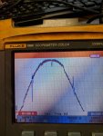
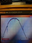
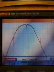
As a preliminary check, I hooked up a motor drive (sans motor) and took readings on the line with the line reactor, with an EMI filter, and with without either of these two things.
I have attached a picture of each.
Now, it appears to me that the notching amplitude has actually increased with both the reactor and the filter.
If you would, please guide me in the right direction.
Thanks in advance,
Mark
I was recently asked to look at the power line feeding a 480VAC 1ø magnetic chuck, which at times refuses to work.
On attaching an oscilloscope to the line, I saw notching occurring, and eventually traced it back to a couple of induction heaters.
It was suggested to me to add a line reactor to clean up the signal feeding the chuck controller.
As a preliminary check, I hooked up a motor drive (sans motor) and took readings on the line with the line reactor, with an EMI filter, and with without either of these two things.
I have attached a picture of each.
Now, it appears to me that the notching amplitude has actually increased with both the reactor and the filter.
If you would, please guide me in the right direction.
Thanks in advance,
Mark