hhsting
Senior Member
- Location
- Glen bunie, md, us
- Occupation
- Junior plan reviewer
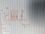
Attached sketch shows incoming service conductors into 1600A main service disconnect. From the 1600A main service phase conductors plus equipment grounding conductors go into trough from which their is a tap to POCO meter then to disconnects #1 to #9 as shown which are either 200A or 100A disconnects. The disconnects feed each tenant.
You see all things up to to meters have POCO lock and may be controlled by POCO making it difficult as to what is line side, load side, service disconnect and location of main bonding jumper(s).
Questions are:
1. What is considered load side and what is considered line side for application of 250.24(A)(5)?
2. Which is service disconnect 1600A switch only or 1600A and #1 to #9 disconnects are all service disconnects?
3. Should main bonding jumper be at 1600A switch only or at 1600A and disconnects #1 to #9? I am aware of 250.24(B) and definition of service NEC Article 100 however not sure what is the service disconnect in this case.
Attachments
Last edited: