Phil86
New member
- Location
- Asheville, NC, USA
I have the following situation and am not sure how to correctly provide main bonding:
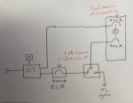
1) The system is 480 V, 3-phase, 4-wire, grounded-wye.
2) The service incorporates a utility-owned CT cabinet for revenue metering.
3) A single set of service conductors leaves the CT cabinet and feeds an enclosed 400 A circuit breaker (ECB). The ECB is service entrance rated.
4) The 400 A ECB feeds an automatic transfer switch. The 3-pole automatic transfer switch feeds a 400 A main breaker panelboard.
5) A second set of service conductors from the CT cabinet feeds a second 400 A breaker in the same panelboard.
6) The two circuit breakers are kirk-key interlocked such that only one can be closed at any point in time.
7) The purpose of the direct feed from the CT cabinet to the panelboard is for temporary maintenance bypass of the 400 A ECB and the ATS. The 400 A ECB and the ATS will be energized during normal operation.
Question: Where should the main bonding occur in the above scenario? I'm struggling with the fact that normally the main bonding would be in the 400 A ECB; however, when operating in bypass, the main bonding would need to be in the 400 A panelboard. I can't figure out how to isolate the two and comply with the NEC. Any help is appreciated.
:?:?