main panel to subpanel conversion

Status
Not open for further replies.

am1954

Member
Location
NY
Occupation
contractor
hey all. we have an application where the electrician put in a generator and auto transfer switch, thus rendering the main panel (200a homeline main breaker panel) into a subpanel. i'm having a back and forth with the electrician, the inspector, and siemens as how to properly isolate neutrals and grounds in this panel, now that the ATS is the first point of disconnect.

i've had multiple conversations with Siemens tech support. first time they told me an auxiliary ground bar was required. second and third time they told me that pulling the bonding screw was all that was needed. the electrician also said that pulling the bonding screw as well as pulling the screw that attaches the neutral bar to the bar that runs behind the main lugs was all that was needed. with all this done, i still get continuity between the neutral bar and the ground bar.

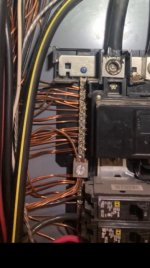
additionally, i'm wondering if the way the 2/0 ground from the ATS is bonded to the rest of the ground bar is correct? it's just supposed to be bonded via the panel and the tiny screws at the top of the ground bar and at the ground lug the 2/0 ground lands on?

unfortunately the catalog number for the panel is inaccessible so i can't get specifics, but wondering if anyone has thoughts based on the picture i'm putting below.
IMG_3930.jpg
 

am1954

Member
Location
NY
Occupation
contractor
ptonsparky, the blk/white is just a neutral to a subpanel. the blk/yellow is the ground that they brought in from the generator transfer switch. i don't know why it's landed that way but electrician said that's how it's done.

agreed that he should be doing these tests (and will most likely make him do the test you suggested). i'm just trying to figure out if this is actually how this should have been done and if it's to code.

p.s. i was told that the right terminal was due to heating in the past. a bunch of 50a 2 pole breakers were pulled from the panel since then. all were landed on that side of the panel for what that's worth.
 

LarryFine

Master Electrician Electric Contractor Richmond VA
Location
Henrico County, VA
Occupation
Electrical Contractor
i've had multiple conversations with Siemens tech support. first time they told me an auxiliary ground bar was required. second and third time they told me that pulling the bonding screw was all that was needed. the electrician also said that pulling the bonding screw as well as pulling the screw that attaches the neutral bar to the bar that runs behind the main lugs was all that was needed. with all this done, i still get continuity between the neutral bar and the ground bar.
Removing the bonding screw will only separate the panel enclosure from the neutral. In addition, every neutral must be on the insulated-from-the-enclosure bus, and every ground only on the connected-to-the-enclosure bus.

Of course, you still read continuity, because the neutral and the EGC are connected together in the ATS. If they weren't, an accidental fault could energize your house instead of tripping the main breaker.
 

am1954

Member
Location
NY
Occupation
contractor
larry, right i spaced out and forgot that continuity was being read from the bonding at the ATS. i guess what i'm confused about though, is that it looks to me like both the neutral and the ground bars appear to be insulated from the enclosure and connected together via the bar that runs behind the main lugs (see attached pic of ground bar). therefore wouldn't pulling the neutral grounding screw isolate them both from the enclosure? maybe unofficially they are bonded via the little screw at the top of the ground bar (or maybe that's an official way of bonding it to the enclosure?)
 

Attachments

  • 111.jpg
    111.jpg
    73.2 KB · Views: 18

suemarkp

Senior Member
Location
Kent, WA
Occupation
Retired Engineer
That big lug in the ground bar is where the EGC from the transfer switch is supposed to land. It isn't supposed to have a bunch of #12 and #14 grounds twisted together and put in that lug. Most ground bars are allowed at least 2 wires per hole in sizes 14-10, and some allow three. You may need to add a 2nd bar.

Not sure if the lug in that bar will take a 2/0 ground. The ground doesn't need to be nearly that large -- a #6 would be acceptable for a 200A upstream breaker.
 

am1954

Member
Location
NY
Occupation
contractor
suemarkp. those wires you are referring to are actually a bare copper #6 (or maybe it's #4 i don't know) that run to a ground rod outside. it's not a bunch of smaller ground wires. there is an additional #6 (or #4) bare egc in the ATS that is run to the same ground bar. i was also confused why they needed a 2/0 ground from the ATS to the MSP. my understanding was that #6 pairs with a 200a breaker, but i don't do generator work so thought maybe there was something else in the code somewhere that was requiring that.
 

suemarkp

Senior Member
Location
Kent, WA
Occupation
Retired Engineer
But there appears to be a single smaller conductor coming out the top side of that large lug. So maybe its a #12 and a #6 both in the same hole? Still not allowed...
 

LarryFine

Master Electrician Electric Contractor Richmond VA
Location
Henrico County, VA
Occupation
Electrical Contractor
i guess what i'm confused about though, is that it looks to me like both the neutral and the ground bars appear to be insulated from the enclosure and connected together via the bar that runs behind the main lugs (see attached pic of ground bar). therefore wouldn't pulling the neutral grounding screw isolate them both from the enclosure?
Yes, they are insulated from the can. For the 4-wire conversion, I remove the jumper. I use the bus with the green screw installed as the EGC bus, and the other, still-insulated bus as the neutral bus.

These days, many panels come equipped with two insulated neutral buses (like your pics) and two EGC buses attached to the enclosure. I always wire panels as if they will become sub-panels some day.
 

am1954

Member
Location
NY
Occupation
contractor
ok. so he should either have the grounds located on the bar that has the neutral bonding screw and remove the jumper (although not sure if this is possible on a homeline panel), or put in an aux ground bar that is connected to the enclosure. in either of those scenarios, i assume the way that the 2/0 ground from the ATS is landed in the panel is ok? and is it ok that there is a 4awg bare ground in both the former main panel as well as one in the ATS that are both running to the same ground rod? or at that point should the 4awg ground in the former main panel be eliminated?
 

LarryFine

Master Electrician Electric Contractor Richmond VA
Location
Henrico County, VA
Occupation
Electrical Contractor
ok. so he should either have the grounds located on the bar that has the neutral bonding screw and remove the jumper (although not sure if this is possible on a homeline panel), or put in an aux ground bar that is connected to the enclosure. in either of those scenarios, i assume the way that the 2/0 ground from the ATS is landed in the panel is ok?
Yes, with paint removed and a bolt or bolt and nut, not a sheet-metal screw.

and is it ok that there is a 4awg bare ground in both the former main panel as well as one in the ATS that are both running to the same ground rod? or at that point should the 4awg ground in the former main panel be eliminated?
I would remove it from the new sub-panel to eliminate neutral current on it.
 
Status
Not open for further replies.
Top