Max % of allowable currrent unbalance in lighting transformer

Status
Not open for further replies.

Smart $

Esteemed Member
Location
Ohio
Please help me,

What is the max % of allowable current unbalance in lighting transformer?
Transformer data: voltage, phases, configuration, kVA...?

Are we talking line current imbalance or lighting load to non-lighting load current imbalance as in the case of delta high leg bank comprised of lighter and stinger pot(s)?
 

vinod

Senior Member
Location
Saudi Arabia
Transformer data: voltage, phases, configuration, kVA...?

Are we talking line current imbalance or lighting load to non-lighting load current imbalance as in the case of delta high leg bank comprised of lighter and stinger pot(s)?


voltage, phases, configuration, kVA...?

V= 480/ 208-120
Phase= 3ph
Connection = Delta /star
KVA = 45KVA

this is a lighting system see attachment.

I have asked about the % of UB current in total load. i.e R-N=74, Y-N= 80.3, B-N=84.8.
As of this figure , is this panel current unbalanced?
 

Attachments

  • Capture.jpg
    Capture.jpg
    122 KB · Views: 5

Smart $

Esteemed Member
Location
Ohio
...
As of this figure , is this panel current unbalanced?
It's unbalanced but not enough for there to be any concern.

The power company may not like it, and doing so would add to power factor penalties if any, but IMO you could completely unload one or two lines and it wouldn't hurt the transformer.
 

Carultch

Senior Member
Location
Massachusetts
I do not know of any for a wye secondary.


If you have a WYE secondary and a DELTA primary, what exactly happens to the unbalanced current?

So given Ias, Ibs, and Ics, as the currents on each secondary line conductor of the wye system, what becomes Iap, Ibp and Icp for the primary line currents?
 

Carultch

Senior Member
Location
Massachusetts
If you have a WYE secondary and a DELTA primary, what exactly happens to the unbalanced current?

So given Ias, Ibs, and Ics, as the currents on each secondary line conductor of the wye system, what becomes Iap, Ibp and Icp for the primary line currents?
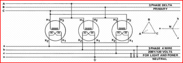
I think I figured it out.

Secondary coil A is connected to primary coil AB
Secondary coil B is connected to primary coil BC
Secondary coil C is connected to primary coil CA

n is the turns ratio between coils, which would be 4 for 120/208V secondary to 480V primary.

Therefore
Iabp = Ias/n
Ibcp = Ibs/n
Icap = Ics/n

Which would mean:
Ia = sqrt(Iabp^2 + Icap^2 + Iabp*Icap)
Ib = sqrt(Iabp^2 + Ibcp^2 + Iabp*Ibcp)
Ic = sqrt(Icap^2 + Ibcp^2 + Iabp*Icap)
 

Smart $

Esteemed Member
Location
Ohio
I think I figured it out.

Secondary coil A is connected to primary coil AB
Secondary coil B is connected to primary coil BC
Secondary coil C is connected to primary coil CA

n is the turns ratio between coils, which would be 4 for 120/208V secondary to 480V primary.

Therefore
Iabp = Ias/n
Ibcp = Ibs/n
Icap = Ics/n

Which would mean:
Ia = sqrt(Iabp^2 + Icap^2 + Iabp*Icap)
Ib = sqrt(Iabp^2 + Ibcp^2 + Iabp*Ibcp)
Ic = sqrt(Icap^2 + Ibcp^2 + Iabp*Icap)
Man... it's difficult trying to keep up with all the different nomenclature used on this board. :blink:

It looks like you are used the law of cosines. Nothing wrong with that method, but we tend to use vector math around here. :D

Let's try this method, as it seems more common.

Primary coil "AC" is paired with secondary "an".
Primary coil "BA" is paired with secondary "bn".
Primary coil "CB" is paired with secondary "cn".

For the sake of polarity, the first letter gets the "dot". I believe this to be the conventional configuration for dry-type transformers.

Configured as such, line currents are respectively primary IA, IB, and IC, and secondary Ia, Ib, and Ic. Therefore in vector parlance...

IA*n = Ia-Ib
IB*n = Ib-Ic
IC*n = Ic-Ia

Delta-WyeBank.gif
 
Last edited:

Jraef

Moderator, OTD
Staff member
Location
San Francisco Bay Area, CA, USA
Occupation
Electrical Engineer
Bottom line, technically the transformer doesn't "care" about current imbalances. In a Delta/Wye transformer, there is an effect of balancing the load side imbalance to the line side. Current imbalance in and of itself is not bad, but if it causes a VOLTAGE imbalance, that's where the trouble starts. So if you have a transformer that is heavily loaded, a current imbalance will have more of an effect on voltage balance than on a transformer that is, say, 50% loaded and because there is a small amount of added heating, in effect your efficiency goes down (depending on the amount of imbalance) as your imbalance exceeds 1%. Any 3 phase motor loads on your secondary side are going to be where the voltage imbalance above 1% shows up, because it makes the motors work electrically harder to do the same amount of mechanical work.
 

Ingenieur

Senior Member
Location
Earth
not an issue
first the load is low, <30 kva (8.9, 9.6, 10.2), utility won't care or even notice
avg is 9.6... -0.7, +0.6
about +/- 7%
very low N current (assuming all 3 ph have ~ the same pf)

you could go 15, 15, 0
as others have said only an issue if it causes an voltage imbalance
 

NewtonLaw

Senior Member
voltage, phases, configuration, kVA...?

V= 480/ 208-120
Phase= 3ph
Connection = Delta /star
KVA = 45KVA

this is a lighting system see attachment.

I have asked about the % of UB current in total load. i.e R-N=74, Y-N= 80.3, B-N=84.8.
As of this figure , is this panel current unbalanced?

Based on this small imbalance in current and looking at the %Z range for 45 kVA dry type transformer which ranged from 2.8% to 5.2%, the worst unbalanced in voltage at the transformer terminals 0.05% by NEMA standards and 0.055% using the IEC standard. So as with most of your replies, I also see no problems. Of course this was assuming 1.0 power factor.

Hope this helps.
 

Phil Corso

Senior Member
not an issue
first the load is low, <30 kva (8.9, 9.6, 10.2), utility won't care or even notice
avg is 9.6... -0.7, +0.6, about +/- 7%
very low N current (assuming all 3 ph have ~ the same pf)
you could go 15, 15, 0, as others have said only an issue if it causes an voltage imbalance

InjunEar...

The extreme distribution you propose seriously impacts neutral current,In! In addition, it results in a circulating-current of ~ 16% in the Xfmr's Prim'y-winding !

Phil Corso
 

Phil Corso

Senior Member
If you have a WYE secondary and a DELTA primary, what exactly happens to the unbalanced current?
So given Ias, Ibs, and Ics, as the currents on each secondary line conductor of the wye system, what becomes Iap, Ibp and Icp for the primary line currents?

Carultch...

1) The currents in the Sec'y or Wye-winding, equal, in both magnitude and power-factor angle, the load currents!

2) The Prim'y or Delta-Winding currents are proportional to the Sec'y winding-current divided by the Xfmr's Turns ratio' i.e., 480/120=4! But, because of the D-Y arrangement, the PF angle is shifted by 30 deg!

3) The line-currents, then are the vector difference of Xfm's D-winding currents! That is, Line-Current, IA = IAB-IBC, IB = IBC-ICA, and IC = ICA-IAB!

Phil Corso
 

Phil Corso

Senior Member
Thanks, Do you know any criteria for the maximum % unbalance current?

There is no standard for quantifying the effect of current-unbalance. However, there are IEEE, NEMA and IEC, formulas for determining the impact of a motor’s unbalanced voltages on its expected insulation-life. It’s called VUF for Voltage-Unbalance-Factor!

I use a modified version called Ampere-Unbalance-Factor or AUF, by taking the square-root of the value derived using the formulas above! The AUF for the OP’s data (assuming unity-PF) for both NEMA and IEC were 2.8%! In addition, neutral-current is 9.1A

My conclusion: impact of unbalanced panel-currents is nil!

Regards, Phil Corso
 
Last edited:

Carultch

Senior Member
Location
Massachusetts
Carultch...

1) The currents in the Sec'y or Wye-winding, equal, in both magnitude and power-factor angle, the load currents!

2) The Prim'y or Delta-Winding currents are proportional to the Sec'y winding-current divided by the Xfmr's Turns ratio' i.e., 480/120=4! But, because of the D-Y arrangement, the PF angle is shifted by 30 deg!

3) The line-currents, then are the vector difference of Xfm's D-winding currents! That is, Line-Current, IA = IAB-IBC, IB = IBC-ICA, and IC = ICA-IAB!

Phil Corso

Cool, thanks.

I've tried an example calculation, and the three delta-side line currents do not add up to zero. A delta transformer doesn't connect to the neutral. So if this delta primary were supplied from another WYE system, how would the WYE system supply this imbalance?

Example calculation:
Ias = 100A
Ibs = 90A
Ics = 80A

Iap = 41.2
Ibp = 36.8
Icp = 39.1

This does not add up to zero, but adds up to 3.75A that would ordinarily be on the neutral.
 
Status
Not open for further replies.
Top