PE (always learning)
Senior Member
- Location
- Saint Louis
- Occupation
- Professional Engineer
Hey Everyone,
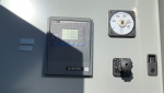
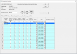
I'm a little new to medium voltage protective relays and I was needing some help with modeling the proper devices in SKM power tools. I'm working with a M20 Sepam Protective Relay and I'm trying to make sure I choose the right information in SKM power tools. This relay is located inside a MCC that feeds a 450 HP Pump. I have attached a picture of the relay and a picture of my options in the SKM library. Can someone please help me with correctly choosing the right information. Is there a way to tell if this relay is DT (Definitive Time) or IDMT (Inverse Definitive Minimum Time)? Also, I'm assuming that this relay is providing protecting for both phase and ground fault. Is there a trick to modeling these properly in SKM?
Best Regards