Megging motor and troubleshooting VFD

Status
Not open for further replies.
Location
US
Occupation
Electrician
I need help. I have a dura pulse gs3 VFD on a 3 phase 480v 3 phase 9 wire motor. VFD trips on ground fault every now and then. It may trio every other time the motor kicks on or every tenth time, it just varies. I’ve isolated my line and load cables to the motor and ran insulation test, all good. Now to the motor. Disconnected all 3 line wires, ran test and got .1 megohm on each phase to ground. Then isolated every wire (disconnected 4-7, 5-8, 6-9 and of course line wires). I get 550 megohms on each phase to ground. Is this motor bad? Is the VFD bugging out? Any help is appreciated.
 

paulengr

Senior Member
Under 1000 V motors minimum is 5 megaohms measured at 500 VDC after 1 minute AFTER temperature correction so realistically if should be 10-20 megaohms or more. This is based on current EASA and IEEE standard 43-2000 standards. So it clearly fails. As far as how or why the way you are doing the test is not right. Just bolt all the leads together and check leads to the motor frame. The coil to coil resistance should be milliohms so for an insulation resistance test on the motor reading different phases is pointless.

Second issue is you may have bearing fluting going on. This is caused because the VFD outputs rectangular waves instead of sine waves. It causes common mode voltage where V1+V2+V3 is not zero. This induces a voltage on the rotor shaft. Normally it can conduct through the bearings harmlessly to ground but if it builds up too much it will arc in the bearings causing pitting and eventually destroys the bearings and leaves a tell tale “fluting” mark on the races. This happens on larger motors even without VFDs. It’s easy to detect. Use a 200 MHz bandwidth scope. Put one probe on the frame. Put the other probe on a metal or carbon brush. Even a chipping hammer works. Measure voltage on the shaft using the brush as a pickup looking at peak voltages. If it’s over a couple volts you have fluting. PM me if you do. We have several solutions for it. Or just have your motor shop tear down the motor since it’s already shot and have a look.

Often VFDs are factory set to trip at 5% “ground fault”. Ground fault being either negative sequence current or often just the vector sum of the three phase currents. The errors of the three CTs contribute and if you can see the reading the residual ground fault measurement (calculation) is quite noisy and bounces all over the place so realistically setting this to 15% as a trip point is a much better setting.

I deal with this issue all the time,
 
Location
US
Occupation
Electrician
If this only trips every once in a while, it shouldn’t be a motor issue right? The motor pumps fluid out of a vessel about every 4-5 mins. It may go 2 hours without tripping. It may go 15 mins. But to me If it was a motor issue it would do it all the time. I’m not familiar with VFDs and rarely have had many motor issues. When they go bad they go bad for me
 

kwired

Electron manager
Location
NE Nebraska
Is it inverte duty rated motor?

How long are conductors between motor and drive?

Is there a line reactor on load side of drive?

Google IGBT reflected wave - you will get better explanations than I can give you.

My experience is if that is the cause the motor is toast though and drive will give a fault every time you try to run it, but maybe you have one that is just on the edge of failure?

I'd also check conductors between motor and drive to make certain there isn't something intermittent there.
 

paulengr

Senior Member
Is it inverte duty rated motor?

How long are conductors between motor and drive?

Is there a line reactor on load side of drive?

Google IGBT reflected wave - you will get better explanations than I can give you.

My experience is if that is the cause the motor is toast though and drive will give a fault every time you try to run it, but maybe you have one that is just on the edge of failure?

I'd also check conductors between motor and drive to make certain there isn't something intermittent there.

Reflected wave burns up the first couple turns. The VFD may it may not show ground fault. Megger may or may not show ground fault. It is obvious on disassembly and will totally fail a surge test. It often also shows up eventually as single phasing or current unbalance.

Six solutions: first is move drive closer to motor. Second is use VFD cable but the improvement is modest, like increasing distance on AB drives from 50 to 80’feet. Third is load reactors which gives moderate distance with a 3% power loss (torque and efficiency). Fourth is dv/dt filter that gives under 1% loss with a smaller filter and better distance for same price as load reactor. Last is sinus wave filter...thousands of feet but they are larger. Finally there is RC terminations that install at motor end and eliminate reflections.

Bearing fluting is when common mode from the drive arcs through the bearings. When it arcs the drive will see a massive ground current surge, often enough to trip the drive but random enough to be hard to pinpoint until you disassemble the motor and look at the bearings.

None of the above work. Need output common mode filters. All other solution
 

petersonra

Senior Member
Location
Northern illinois
Occupation
engineer
.1 megaohm doesn't raise a flag?

I've never raised the GF settings before, but the motor or conductors were always faulted.
It raises a flag but it doesn't seem possible that you could have that bad of an insulation problem inside the motor without the motor burning up. I personally suspect some kind of measurement error.

Think about the internal arrangement of the coils in a motor. They're not all connected together so how could you get the same exact reading on all of them. It's just a suspicious thing.
 

retirede

Senior Member
Location
Illinois
It raises a flag but it doesn't seem possible that you could have that bad of an insulation problem inside the motor without the motor burning up. I personally suspect some kind of measurement error.

Think about the internal arrangement of the coils in a motor. They're not all connected together so how could you get the same exact reading on all of them. It's just a suspicious thing.

I think he stated that the .1 meg was observed before he separated the motor leads. Once separated, the readings were normal.

Either measurement error or a problem with the insulation on the motor leads.
 

kwired

Electron manager
Location
NE Nebraska
It raises a flag but it doesn't seem possible that you could have that bad of an insulation problem inside the motor without the motor burning up. I personally suspect some kind of measurement error.

Think about the internal arrangement of the coils in a motor. They're not all connected together so how could you get the same exact reading on all of them. It's just a suspicious thing.
IGBT reflected wave degradation- unless maybe you know what to look for will leave a pretty clean looking motor winding yet drive will trip on ground fault before it gets very far into acceleration. I've taken motors that failed in this manner and connected them across the line - boom - the problem is then obvious. The drive just happens to sense this before there is significant fault current and never makes obvious destruction appear.
 

Jraef

Moderator, OTD
Staff member
Location
San Francisco Bay Area, CA, USA
Occupation
Electrical Engineer
All well and good, but INTERMITTENT tripping would mean it is not a motor winding insulation breakdown situation in my experience, because when that happens, it ALWAYS happens.

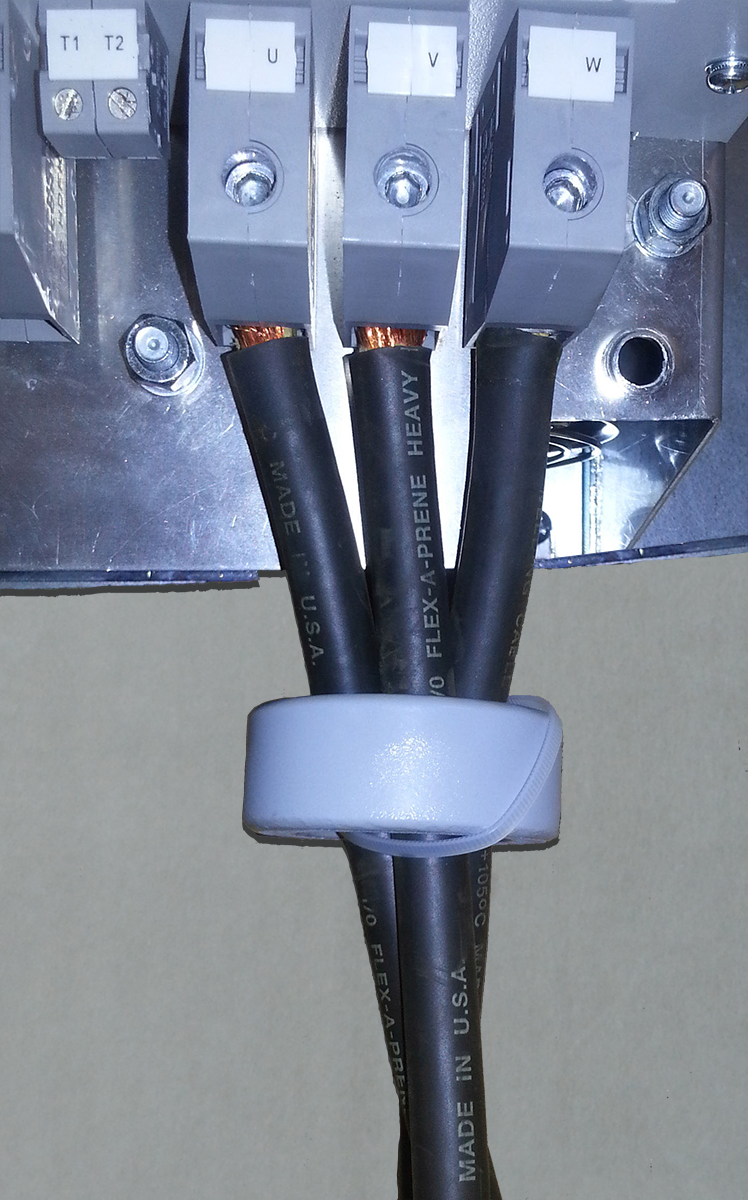
Intermittent tripping on GF is sometimes an issue with cable capacitive coupling, i.e. because of the high speed DC pulses coming from the VFD transistors, the motor leads are acting like capacitors and depending on exactly when the output sine wave is generated between phases, sometimes the capacitive charging current is unequal between them and that is interpreted by the VFD's GF trip algorithm as non-returning current, ergo it must be leaking to ground. This happens mostly when you have not used VFD cable AND the loose conductors in the conduit were not "triplexed" (twisted together to maintain a consistent geometry). This can often be ameliorated by putting in a "common mode choke" on the output conductors, a ferrite core through which the motor leads are run.

ferritering_panelbg.png
 

paulengr

Senior Member
It raises a flag but it doesn't seem possible that you could have that bad of an insulation problem inside the motor without the motor burning up. I personally suspect some kind of measurement error.

Think about the internal arrangement of the coils in a motor. They're not all connected together so how could you get the same exact reading on all of them. It's just a suspicious thing.

1 Megaohm is a red flag unless you mess up the measurements. It could be lots of contamination and still work but normally this is low enough that it might run for 5 seconds or 5 hours but it’s going to trip and only get worse if it’s damaged insulation. The trouble with Megger tests is that contamination, moisture, and damage all look the same with no good way to distinguish between them.

Which leads you to a cause..,with the coils connected the coils themselves are essentially shorts so measuring insulation resistance at any lead SHOULD be identical. If you separate them most of the time it still reads pretty close to the same because the same winder made the coils the same way, used the same slot insulation, etc. And if it’s contamination it’s pretty uniform most of the time. Reflected wave damage is progressive and uniform. Bearing arcing is common mode so appears uniform, too. It’s only if you have say damage in one slot that things change up. But damage of this type, down in middle of the slot, other than say overload, is actually relatively rare. It does happen but it’s not something we see every day. Among other things a surge test won’t detect it at all.
 

garbo

Senior Member
I need help. I have a dura pulse gs3 VFD on a 3 phase 480v 3 phase 9 wire motor. VFD trips on ground fault every now and then. It may trio every other time the motor kicks on or every tenth time, it just varies. I’ve isolated my line and load cables to the motor and ran insulation test, all good. Now to the motor. Disconnected all 3 line wires, ran test and got .1 megohm on each phase to ground. Then isolated every wire (disconnected 4-7, 5-8, 6-9 and of course line wires). I get 550 megohms on each phase to ground. Is this motor bad? Is the VFD bugging out? Any help is appreciated.
Worked on several hundred VFDS. Best to have at least 10 megohms to ground. Motor has to be at a complete stop before meggeting. About 7 years ago I had trouble with 3 or 4 Danfoss VFD'S tripping out up to 15 times a year on what they called EARTH FAULT. Drove me crazy. Meggered great every time. Finally called our great Dangoss service tech. He asked for the model & serial # and
promised to have it squared away the next morning. Turns out that the ribbon cable between main board and the LCP ( Thats what Danfoss calls the control panel ) were defective. Never had another earth fault after that. Danfoss & A&B always extra helpfull. Forget about ABB. They always give me the run around.Best pratice try to keep distance from VFD to motor less then 100 feet. Had three 60 HP drives that had to be a few hundred feet away from roof top tower fans but did not give any problems.
 

paulengr

Senior Member
Worked on several hundred VFDS. Best to have at least 10 megohms to ground. Motor has to be at a complete stop before meggeting. About 7 years ago I had trouble with 3 or 4 Danfoss VFD'S tripping out up to 15 times a year on what they called EARTH FAULT. Drove me crazy. Meggered great every time. Finally called our great Dangoss service tech. He asked for the model & serial # and
promised to have it squared away the next morning. Turns out that the ribbon cable between main board and the LCP ( Thats what Danfoss calls the control panel ) were defective. Never had another earth fault after that. Danfoss & A&B always extra helpfull. Forget about ABB. They always give me the run around.Best pratice try to keep distance from VFD to motor less then 100 feet. Had three 60 HP drives that had to be a few hundred feet away from roof top tower fans but did not give any problems.

5 megaohms is good TEMPERATURE CORRECTED. So unless it’s a hot summer day the actual reading will be higher. In winter 300% higher. So I corrected values might need to be 10-20 megaohms. This is for under 1000 V.


Sent from my iPhone using Tapatalk
 
Status
Not open for further replies.
Top