Motion sensor to control contactor coil

Status
Not open for further replies.

ike5547

Senior Member
Location
Chico, CA
Occupation
Electrician
I'm having a problem with a chattering contactor connected to motion sensors with triacs. Apparently triacs and inductive loads don't work well together. I was wondering if anyone here has any reason to suspect that this problem cannot be fixed by using a Solid State contactor in place of the inductive coil contactor.

Thanks

PS) This is for lighting so I'm hoping this is the right sub-forum.
 

GeorgeB

ElectroHydraulics engineer (retired)
Location
Greenville SC
Occupation
Retired
Apparently triacs and inductive loads don't work well together. I was wondering if anyone here has any reason to suspect that this problem cannot be fixed by using a Solid State contactor in place of the inductive coil contactor.
I've never had a problem with triac outputs and coil contactors; I have had problems with triacs driving solid state relays. Leakage current of the triac outputs can do some strange things which a load resistor has helped in some situations.

Can you give some specifics?
 

iwire

Moderator
Staff member
Location
Massachusetts
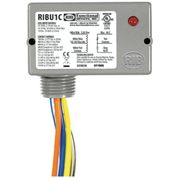
I would just put in a small pilot relay such as a "RIB"
ribu1c2.jpg


or an Ice Cube.
image.php
 

ike5547

Senior Member
Location
Chico, CA
Occupation
Electrician
Can you give some specifics?

It's basically the exact same problem outlined in this thread from a long time ago (without a bypass switch). The OP never followed up on how it ultimately worked out.

http://forums.mikeholt.com/showthread.php?t=79900

I have (2) ceiling mounted PIR motion sensors covering a 1000 sq. ft. floor space. The sensors are to control a 120v contactor coil, which will in turn control the feeds to a number of switch banks on (3) fluorescent and incandescent lighting circuits.

When a motion sensor activates it pulls in the coil just fine. After the sensor automatically switches off on the off delay the contactor drops out, then pulls back in, then drops out, then pulls back in repeatedly. Thunk-thunk . . . thunk-thunk . . . thunk-thunk . . . etc. I installed a 40 watt incandescant light bulb across the contactor coil and it started working normally. I then tried a 6 watt light bulb and that seemed to work. I then tried (4) 1 watt, 1K resistors in series across the coil (3.6 watts total i think it was) and it didn't work. I then replaced the 6 watt lamp and that inexpicably stopped working as well.

I later found out reading on these forums that even a large wattage lightbulb is a temporary solution and would trigger a call back eventually.

I read of something called a "snubber" which is a capacitor and resistor installed in series across the sensors but the calculations for sizing seem beyond my pay grade.

I'm getting a quote on some new sensors with isolated contacts and I'm confident that I'm going to resolve the situation with those, but was wondering if a solid state contactor would do the job and allow me to keep using the $40 ceiling mount sensors I found.
 

gar

Senior Member
Location
Ann Arbor, Michigan
Occupation
EE
140223-1606 EST

My guess is that your motion sensors are two wire devices. These two wire devices require a sufficiently low impedance load on the output such that when the sensor is off that there is sufficient current to provide adequate power to the sensor electronics for the electronics to operate properly. A cheap and dirty bad way to design a general purpose circuit. A three wire device, one requiring a neutral connection, would probably solve the problem. The problem is not caused by a Triac output.

You need to know how devices work in order to efficiently troubleshoot problems. Learn about basics, and avoid hearsay reasons. Study electronic circuits and devices.

That the load is partially inductive is not really the problem, but rather the load in the off state is a higher impedance than when energized, and there is insufficient current to power the electronics. A two wire sensor with an electro-mechanical output contact (isolated) is not a solution either. Nor is a solid-state contactor likely a solution to your problem.

A 1000 ohm 25 W power resistor as a shunt across the contactor coil probably would solve the problem based on your light bulb experiment. At 120 V this will continuously dissipate 14.4 W. At $ 0.16 / kWh the cost per year of the wasted energy is 126 * 0.16 = $ 20. A 25 W Ohmite resistor dissipating 15 W will have a long life with good air circulation.

.
 

gar

Senior Member
Location
Ann Arbor, Michigan
Occupation
EE
130223-1557 EST

A 3 mfd metalized polypropylene 275 VAC capacitor is about 850 ohms at 60 Hz, and add a 100 ohm series resistance for current limiting and the impedance would be less than 1000 ohms. This will dissipate about 2 W.

.
 

ike5547

Senior Member
Location
Chico, CA
Occupation
Electrician
130223-1557 EST

A 3 mfd metalized polypropylene 275 VAC capacitor is about 850 ohms at 60 Hz, and add a 100 ohm series resistance for current limiting and the impedance would be less than 1000 ohms. This will dissipate about 2 W.

.

How did you come up with this and would you place it in series or parallel?
 

gar

Senior Member
Location
Ann Arbor, Michigan
Occupation
EE
140223-2334 EST

ike5547:

So your motion sensor needs to be tested.

But, first, a Triac is similar to a pair of back-to-back SCRs. Thus, looking at the conduction characteristics of and SCR is sufficient to get a basic understanding.

If the gate current to an SCR is zero (the control electrode -- similar to the grid in a thyratron), then there is no conduction between anode and cathode of the SCR for either polarity of the anode to cathode voltage up to a breakdown voltage. However, there is a very small leakage current.

If there is a sufficient forward gate current and sustained, then the SCR anode to cathode looks similar to a diode. Conduction with a small forward voltage drop between anode and cathode when the anode is positive relative to the cathode. And virtually no conduction when the polarity is reversed.

If the gate trigger current is applied as a short pulse some time after a positive voltage is applied to the anode, then until the trigger current pulse occurs there is no anode to cathode current flow, and after the trigger the SCR becomes conductive and remains in this state until the anode-cathode current drops below a low holding current level.

So a sustained positive gate current will keep the SCR continuously conductive so long as the anode is slightly positive relative to the cathode. Just like a mechanical switch was closed.

By putting SCRs back-to-back we get controlled conduction for both polarities. A Triac is an integrated device that performs very much like the back-to-back SCRs, except two different gate drive circuits are not required. A positive gate current to the single gate of the Triac triggers conduction in both directions of the anode-cathode polarity.

Is your motion sensor really a three wire device, or is the third wire simply an EGC wire?

A test to try. Take one sensor. Apply 120 V input. Use pure resistance as the load. Adjust the load to determine an approximate maximum resistance for which conduction occurs. Then try with your contactor load.

I have a Cooper VS306U. This device is a three wire device and sounds like it has a relay output. I have not opened it yet. The sensor works fine with a 5 K resistive load. Then I tried a very small Potter & Brumfield relay. It produced the results you experienced. If the output contact is an electromechanical relay, then turn off of the inductive load may not occur at a current zero crossing, and a large inductive transient might occur that would retrigger the on function. It is late and I will look at it more tomorrow.

Your other question I will answer tomorrow.

.
 

gar

Senior Member
Location
Ann Arbor, Michigan
Occupation
EE
140224-0822 EST

ike5547:

I opened the motion sensor and there is a little red box that is almost certainly an electromechanical relay. There is good reason to use this instead of a Triac and heatsink. This application is simply an ON-OFF type of function and does not require phase shift control. The power loss in a Triac type switch contact is much greater than a pair of silver contacts. Possibly 1000 times more. Thus, no need for a big heatsink.

I don't want to dig further into the circuitry to try to understand why the circuit is doing what we observe. The off time delay function appears to be analog and for the time periods available, and component sizes this probably means very high impedance circuits. These could be vulnerable to transient voltages from switching an inductive load at a non-current zero point.

Thus, it makes sense to limit very rapid changes in voltage from an inductive kick with a snubber or resistor.

With my small relay a 3 mfd capacitor and 33 ohm resistor were sufficient to prevent the problem. This resistor-capacitor series combination is placed in parallel with the relay coil.

The current thru an inductor can not be changed instantaneously. Thus, if current is flowing in an inductor and the circuit is instantaneously opened, then the inductor will generate a voltage across its terminals sufficient to maintain the current flow, and this produces a very large voltage (resulting in arcing) unless there is some sort of shunt current path. A diode can be used in a DC circuit for this purpose. In an AC circuit some other transient limiter is needed. A capacitor can be used in the AC circuit. The purpose of the series resistor with the capacitor is to limit the current thru the controlling switch when the capacitor has an initial charge of 0 and the turn on point in the AC cycle is at a voltage peak.

How did I select the capacitor size? You indicated that something in the 10 W range for a light bulb would prevent the problem. 10 W at 120 V is 1440 ohms. Thus I judged a 1000 ohm shunt on the relay coil would solve your problem. The capacitive reactance of 3 mfd at 60 Hz is Xc = 1/(2*Pi*f*C) or 10^6/(6.28*60*3) = 884 ohms. Adding 100 ohms resistive in series produces an impedance of sq-root of (884^2 + 100^2) = sq-root of 791,000 = 890 ohms.

The capacitor size has to be large enough to limit the dv/dt (rate of change of voltage with respect to time) to a value sufficiently below whatever is the threshold of the device with a problem.

Does this make any sense to you?

.
 

ike5547

Senior Member
Location
Chico, CA
Occupation
Electrician
Does this make any sense to you?

.

Yes and thanks. It was a good post. I worked through the numbers you provided a couple of days ago with the same formulas. If you search around the web you'll find that this is not an uncommon problem. I consider it a design flaw, personally. As far as adding a load, purely resistive or otherwise, this has been attempted by others with only temporary success. As I indicated in my second post the 6 watt lightbulb only worked the first day I tried it and failed on the second attempt. The sensors are 3-wire w/neutral. There is no equipment ground. I'm experienced enough not to purchase 2-wire devices for this application.

I've ordered another set of sensors with a set of isolated auxilary cotacts. I'm confident that this is the best solution rather than experimentation with resistance and capacitance combinations across the load. I will follow up on how it works out.

One thing I'm still wondering, however, is if a solid state contactor would have worked on this.

Thanks for your help.
 

gar

Senior Member
Location
Ann Arbor, Michigan
Occupation
EE
140225-2121 EST

ike5547:

I am glad you understand what a 3 wire dimmer or sensor is. Several years ago when I called Lutron to determine which if any of their dimmers were of a 3 wire type the person I talked with had no idea what such a device was.

From the limited experiment I ran I believe that the sensor is very sensitive to high dv/dt transient noise. And this seems to be a result of bad engineering.

The big difference between my initial comments and where the thread has evolved is that the sensor output switch is a mechanical relay instead of a Triac.

Would a solid-state contactor solve the problem? I believe so. Also a small solid-state isolated relay controlled from the sensor, and used to switch your present contactor should solve the problem. I believe that in some manner the inductive kick from a mechanical contact switching your contactor coil is the cause of the problem. By using a solid state relay (or contactor) as the load on the sensor you essentially have a resistive load on the sensor. Also a solid state relay will turn off at a current zero crossing, at least an SCR or Triac type, and thus minimize the inductive kick from controlling the contactor coil, and any inductive kick from the final load if the final switch is a solid state relay.

A sufficiently large snubber shunt across the contactor will also reduce the dv/dt noise. I believe your 6 W bulb was marginally too high a resistance. The point of using a capacitor as the snubber is that properly designed life can be very many years and also not dissipate much energy.

Using your isolated contact sensors try to keep the wires associated with the mechanical contactor coil away from near proximity to the sensor. If the isolated contacts are still mechanical, then you will still have high dv/dt noise from switching the contactor coil.

.
 

gar

Senior Member
Location
Ann Arbor, Michigan
Occupation
EE
149226-1006 EST

ike5547:

I ran another experiment using an Opto-22 OAC5 solid-state relay to control an AB #2 motor starter (50 years old --- means it is large compared to a present day contactor of the same rating). The OAC5 is a 5 V DC input so I made a resistive divider and a rectifier and filter driver.

The contactor and sensor were from the same outlet, but different cords. There was no incorrect operation of the sensor.

A one package unit that could perform this function is the Opto-22 120A10. See http://www.opto22.com/site/pr_details.aspx?cid=3&item=120A10 . Input control is 85 to 280 V 60 Hz AC. Apparently designed to pull-in at 85 V and tolerate up to 280 V. Drop-out 10 V AC. Turn on and off occur within 1/2 cycle. Nominal load side voltage rating 120 V.

.
 
Last edited:
Status
Not open for further replies.
Top