Multiple EOL on same circuit

Status
Not open for further replies.

Matt229

Member
Location
Allentown, PA
Occupation
Builder
This is not a do-it-yourself project, we have licensed electrician, plumber, engineer and architect. We recently passed our Mechanical, Plumbing, Electrical, and Framing inspections. We are located in a city where we have required permits and inspections. Our fire alarm system will be tested, inspected, and monitored by a licensed fire company. We have a horn/strobe wiring question, and prior to insulation we want to make sure the wiring of the horn/strobes is correct.

We are wires for a Silent Knight 6700 in a brewery that I'm building. While running the horn/strobe wire in tandem I have run the wire A to B to C, A to D, B to E. With C, D, and E end of line. I plan to put resistors at C, D, and E. Is there any problem with this configuration? The link below show the wire diagram.

I am also attaching our MEP 104 - Fire Safety Plan.


Multiple EOL on same circuit
MEP 104 - Fire Safety Plan
 
You should check with the manufacturer of the alarm system.

From what I know, a second EOL resistor "may" lower the voltage in the loop below alarm level, and a third will almost certainly be in a constant alarm state
 
I believe you need four wires down each side branch, so you have only one loop with no parallel branches, electrically speaking, and so there is only one actual end of the line.
 
Here's a good explanation:

Many alarm systems, including the house I bought, have the EOL resistors right at the alarm panel. This is wrong -- either the technician was lazy or clueless as to why you need them in the first place. Long ago, single EOL was the the norm (even if miswired) and now double EOL is preferred, if possible, since it covers more failures.
 
Many alarm systems, including the house I bought, have the EOL resistors right at the alarm panel. This is wrong --
I don't understand that statement. In a class A Fire alarm the loop starts at the panel and ends at the panel including the EOL resistors. Sure makes it easy to find them.
 
I don't understand that statement. In a class A Fire alarm the loop starts at the panel and ends at the panel including the EOL resistors. Sure makes it easy to find them.
Yes, where the loop ends is where the EOL resistors should be...wherever that is.

A lot of lazy/clueless alarm guys, at least on burglar alarm systems, put the EOL resistor at the *start* of the loop -- as in, right at the loop terminals. That makes the panel electronics happy, but defeats the enitre purpose of a EOL resistor.
 
The EOL resistor works as a line monitor.

If a line opens, the panel senses that the resistance is missing.

If the lines are shorted together, the panel triggers the alarm.

Parallel lines with multiple resistors can not monitor the lines.

Only unused loops should have resistors at the terminals.
 
Thanks everyone, I'm making one loop with one EOL resistor, it turns out I don't have to do too much rewiring in order to get this done correctly. I'm not sure what "TTHH" is saying about a double EOL now being the preferred pattern.
 
Thanks everyone, I'm making one loop with one EOL resistor, it turns out I don't have to do too much rewiring in order to get this done correctly. I'm not sure what "TTHH" is saying about a double EOL now being the preferred pattern.
For burglar alarms anyway...(from that link I posted)...

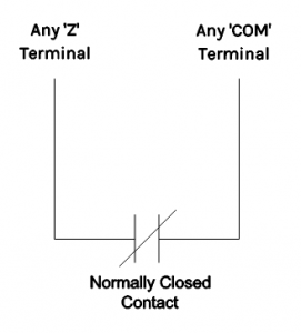
Normally Closed Loops – No EOL​

This is the simplest circuit and also the one with least protection from wiring faults. In this configuration, the circuit is not supervised for open or short circuit conditions. This is simply a normally open contact placed between Z and COM terminals.
  • Zone normal or short circuit: 0Ω
  • Zone violated or open circuit: ∞Ω
Normally Closed Wiring Diagram
Wiring diagram for Normally Closed (no End-of-Line resistor) circuit.

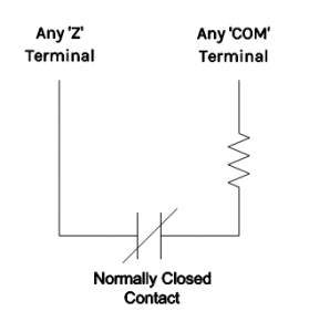
Single End-of-Line Resistor​

This is the default circuit configuration. As the name implies, it uses only one EOL. The circuit is supervised against a short circuit, but there is no differentiation between a violated zone and an open circuit.
  • Zone normal: 5600Ω (for DSC control panels)
  • Zone violated or open circuit: ∞Ω
  • Short circuit: 0Ω
Single EOL Wiring Diagram
Wiring diagram for single End-of-Line resistor circuit.

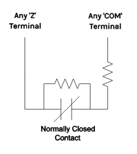
Double End-of-Line Resistor​

This is the most secure wiring type. With double End-of-Line resistor wiring, the control panel is able to differentiate between four conditions:
  • Zone normal (contact closed): 5600Ω (for DSC control panels)
  • Zone violated (contact open): 11,200Ω (for DSC control panels)
  • Open circuit: ∞Ω
  • Short circuit: 0Ω
Double EOL Wiring Diagram
Wiring Diagram for double End-of-Line resistor wiring.
 
This is not a do-it-yourself project, we have licensed electrician, plumber, engineer and architect. We recently passed our Mechanical, Plumbing, Electrical, and Framing inspections. We are located in a city where we have required permits and inspections. Our fire alarm system will be tested, inspected, and monitored by a licensed fire company. We have a horn/strobe wiring question, and prior to insulation we want to make sure the wiring of the horn/strobes is correct.

We are wires for a Silent Knight 6700 in a brewery that I'm building. While running the horn/strobe wire in tandem I have run the wire A to B to C, A to D, B to E. With C, D, and E end of line. I plan to put resistors at C, D, and E. Is there any problem with this configuration? The link below show the wire diagram.

I am also attaching our MEP 104 - Fire Safety Plan.


Multiple EOL on same circuit
MEP 104 - Fire Safety Plan
You have t-tapped the horn strobe circuit, which is STRICTLY forbidden.
 
Status
Not open for further replies.
Top