Option 2 comes closest.,
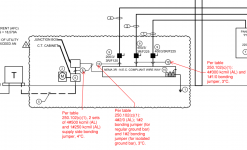
If you are using PVC conduits I would assure the CT cabinet was bonded to the neutral, bond my wireway to the neutral and connect m,y GEC to that terminal, install your 4/0 bonding jumper to bond the j box and bond my disconnects by the MBJ to the neutral.
With PVC no other bonding jumpers are needed,
250.92 states that metallic service raceways must be bonded and the "standard locknuts and bushings shall not be the only means"
The CT cabinet is normally bonded by connecting the cabinet to the neutral conductor.
The j box and wireway can be bonded by connection to the neutrals, or by connection to the bonding jumper you show, or my the use of grounding type lockouts (if no concentric or eccentric ko's are present).
Likewise the conduits can be bonded using bonding locknuts or bushings.
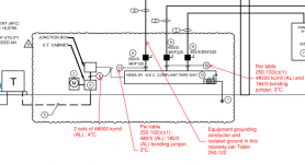
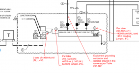
Were I to install it without specifications I would go PVC. If I had to use metal conduit, . I likely would not worry about bonding jumpers but would assure the CT cabinet is connected to the neutrals and I would use grounding locknuts or bushings on each conduit to bond them and bond my neutral in the wireway and connect my GEC to that terminal also (as shown).
Others might do it differently but the end result would be all metallic raceways, boxes, and wireways containing service conductors be bonded by proper locknuts or bushings or by proper sized jumpers.
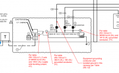
Your disconnects would have MBJ (assuming there is no service disconnect ahead of these) so they would be bonded and the grounding locknut or bushing on the supply conduit would bond those conduits,.
If you had eccentric knockouts bond bushing would be required instead of locknuts and you would use jumpers sized as shown on your drawing tp connect those bushings to the neutral terminals.