Need help with 2 phase (?) transformer

Status
Not open for further replies.

edgarp

Member
Location
East Tennessee
I apologize in advance if this is a silly question, but it's confusing to us....

We have a very old GE transformer that is called a "two phase transformer" in all our old drawings. It's basically got a three phase 480V supply with single phase 120V out. A 1/2 hp reversible single phase motor runs off the supply.
The transformer nameplate shows:
60Hz, 0.12 kVA, 480V, 3ph, 3W - 120/126/132/138V, 2ph, 4W sec., #9T21Y7821

I have a diagram but don't know how to attach it to this post (help please if anyone wants to see it). However, the primary appears to be just a three phase wye (H1, H2, H3), and the secondary has two windings 90 degrees apart with taps in each coil for the various voltages. One end of each goes to the neutral and the other ends go to "phase 1" and "phase 2".

The bottom line is that we are looking to replace this transformer, but we can't take it out of service to really look at it. It's close to 50 years old, and it's the only one we have to supply 5 critical motors. We've contacted GE but with no luck since it's so old and they've moved their specialty transformer operation out of the country.

I guess my questions are:
1) Is anyone here familiar with this type of transformer?
2) Can I replace this transformer with a standard three phase, and still have the single phase secondary, and be able to reverse my motors?
3) Why is it called "two phase"? This is what is throwing off some of our engineers. I know that the motors are single phase and I know that the supply is single phase, but does calling it a 2-phase offer clues as to the design? I think it has somethign to do with the way we are reversing the motors - just swapping phases 1 and 2 with a mechanical interlock.

Again I apologize if this is a silly question, but we are limited in our transformer knowledge at my plant. Thanks for any help!
 

charlie b

Moderator
Staff member
Location
Lockport, IL
Occupation
Retired Electrical Engineer
The term ?two phase? refers to a power supply system in which there are two phases and they are 90 degrees out of phase with each other. It is archaic, and I didn?t expect it to still be in use anywhere. So it that is what you really do have, then you are unlikely to find a replacement for the transformer.

What really matters, however, is the motors themselves. What are their ratings? Are they all, for example, single phase, 120 volt, fractional horsepower motors? If so, then you can get a three phase, 480 to 120/208 volt transformer, and use it to supply each motor with its required power source. You might need to get a small distribution board, as the connection point between the transformer and the motors. Much depends on what you already have in place.

As to posting images, if you have a JPEG (some other formats also work) on your hard drive, then when you post a new thread or a reply to an existing thread, look for the link ?manage attachments? towards the bottom of the page. It will allow you to upload an image directly from your computer.

Welcome to the forum.

p.s. There are neither silly questions nor stupid ones, other than the ones not asked.
 

jim dungar

Moderator
Staff member
Location
Wisconsin
Occupation
PE (Retired) - Power Systems
Your description of the transformer nameplate conforms to a true two-phase unit. 75 years ago this type of distribution system was not un-common, although it was eventually phased out and replaced with a three-phase system instead.

Is your load really only a single motor 1/2HP motor? Is the motor only wired to one phase conductor and the neutral? What does this motor drive? 2-phase motors can be close relatives to 'servo-motors'.
 

edgarp

Member
Location
East Tennessee
Thank you charlie b for your response. There are 5 motors, all 1/2 hp 1725 rpm, vintage Reliance Type CM (PSC?), 115V. I question them being Permanent Split Capacitor, since the wiring diagram doesn't show the capacitor. But I don't believe that really makes a difference here.

Unfortunately, the motors and transformer are not always accessible - otherwise I'd have more information, like resistance readings for both the primary and secondary. I did find the original GE connection diagram, and looking at it more closely, it actually looks like a Scott Tee connected primary, with 2 legs, one center tapped to the other. In that case, we can supply the three phase for the primary, even though it is really a 2 phase winding. Would it make sense that we have the three phase input, with two phases output - but we are using just one phase for one direction of rotation, and the other phase for the reverse direction?

We'd love to be able to put a replacement transformer in without significant modifications to the system, but I am afraid that may be the best route. At this point we don't want to take the existing one out of service to send it to a custom rebuilder to copy the design. We can't live without it for any length of time!

I see at the bottom of the page where it shows the posting rules, and at this point, I am not yet allowed to post attachments. I hope that will change as I use the forum more.
 

LarryFine

Master Electrician Electric Contractor Richmond VA
Location
Henrico County, VA
Occupation
Electrical Contractor
Ed, first of all, welcome to the zoo! :smile:

Does each motor have two or three wires supplying it? You mentioned using phases for reversal (but with a '?'), suggesting three or four wires to each motor.

If you still have trouble posting your diagram, you could always email it to one of us. I'd be happy to host it and link to it here for you. Lettuce know. :D
 

ron_o

Member
I apologize in advance if this is a silly question, but it's confusing to us....

We have a very old GE transformer that is called a "two phase transformer" in all our old drawings. It's basically got a three phase 480V supply with single phase 120V out. A 1/2 hp reversible single phase motor runs off the supply.
The transformer nameplate shows:
60Hz, 0.12 kVA, 480V, 3ph, 3W - 120/126/132/138V, 2ph, 4W sec., #9T21Y7821

[...snip...]


I'm really curious how this was solved. The motors you have are single phase. Why not just find out what what transformer you need for the single phase motors and go from there.

But I'm curious. How can you have a single phase motor run off a 2 phase system?
 

izak

Senior Member
Location
Springfield, MO
3 circuit conductors.

phase A plus 'neutral'(center tap) = forward
phase B plus 'neutral'(center tap) = backward

change phases with interlock and it changes rotation.

ive never seen anything like that...
 

Mr. Wizard

Senior Member
Location
Texas
3 circuit conductors.

phase A plus 'neutral'(center tap) = forward
phase B plus 'neutral'(center tap) = backward

change phases with interlock and it changes rotation.

ive never seen anything like that...

Me either. I have never heard of that style of transformer, with the secondary windings 90 deg. apart. Also seems it would be brutal on the motors to change rotation so abruptly. edgarp, my curiosity is killing me, what kind of machinery uses these motors? The plant you work in must have some really old, neat equipment :smile:
 

cadpoint

Senior Member
Location
Durham, NC
Me either. I have never heard of that style of transformer, with the secondary windings 90 deg. apart. Also seems it would be brutal on the motors to change rotation so abruptly. edgarp, my curiosity is killing me, what kind of machinery uses these motors? The plant you work in must have some really old, neat equipment :smile:


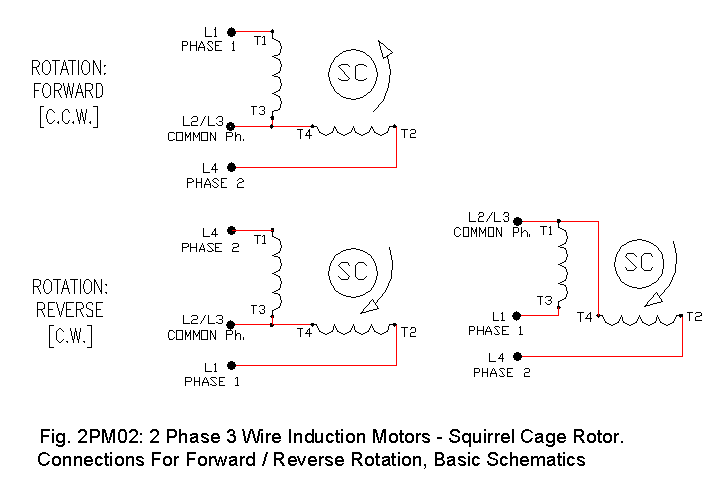
Is this it ?
2pm02.gif


I found it looking HERE looking for 2 phase motors ...

Hey, they all seem 90? apart! :)
 
Last edited:

jim dungar

Moderator
Staff member
Location
Wisconsin
Occupation
PE (Retired) - Power Systems
3 circuit conductors...
I do not remember ever hearing how these motors are actually wired.

Simply adding a neutral point between two conductors does not magically create a new phase. Yes it does create a new relationship by creating a new reference point, but you still only have the original single voltage between what you call Phase A and Phase B.

The 2-phase transformer described by the OP has (2) groups of 'phase conductors' + (1) neutral conductor.
 

jim dungar

Moderator
Staff member
Location
Wisconsin
Occupation
PE (Retired) - Power Systems
Me either. I have never heard of that style of transformer, with the secondary windings 90 deg. apart. Also seems it would be brutal on the motors to change rotation so abruptly.
Why do you think it would be any more brutal than the way we reverse a three-phase or a single-phase motor?
 
Status
Not open for further replies.
Top