Neutral bring to disconnect

Take a look at NEC 2017 Article 250.28(D)(3). That would allow sbj in swbd and in fire pump controller/ats and no sbj in swbd. If outdoor was not allowed then it should say something. Correct or incorrect?
I assume that is a typo, and "no SBJ in SWBD" should be "no SBJ in transformer (source)".

Just because 250.28(D)(3) presents two options doesn't mean that some other section can't limit you further in some situations. And 250.30(A)(1) plus 250.30(C) say that "If the source is located outside the building or structure supplied, a system bonding jumper shall be installed" at the source.

So of the two options 250.28(D)(3) presents, 250.30(A)(1) plus 250.30(C) removes one of the options when "the source is located outside the building or structure supplied." That means you can only use the "the system bonding jumper for each enclosure" option of 250.28(D)(3) when the source is in the building supplied.

Cheers, Wayne
 
A outdoor 13.8 kV system is basically a utility system if it were utility owned they would connect the secondary neutral to a GES at the transformer vault.
While bonding and earthing are related, the OP's questions are related to bonding and the location of bonding jumpers, and not directly to earthing and the location and connection to GESs.

Cheers, Wayne
 
While bonding and earthing are related, the OP's questions are related to bonding and the location of bonding jumpers, and not directly to earthing and the location and connection to GESs.

Cheers, Wayne
By 'earthing system' I mean a descriptive IEC designation of how the grounded conductor, protective conductors (equipment grounding conductors and or supply side bonding jumpers), and the Grounding Electrode System (GES) are arranged relative to the power supply and the relative location of the Main or System Bonding Jumper(s).

I read threads like this and cant help but think the users of the NEC would benefit from understanding and following simple IEC style designations.
IEC Designations consist of letter codes describing the relationship between the source and the Grounding Electrode System(s) (GES), and the conductors providing the grounded and protective functions, The meanings of the letters are as follows:

First Letter (pick one):
"T" - A power supply that is directly connected to a Grounding Electrode System (GES).
"I" - A power supply that is isolated from earth or connected only through a resistance or impedance.

Second Letter (pick one):
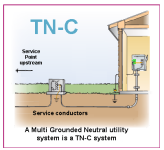
"N" - A current carrying conductor of the power supply that is intentionally connected to a GES. This conductor may be the neutral point of a wye system, the center tap of a single-phase system, or any other intentionally grounded conductor, including corner-grounded or end-grounded systems.
"T" - A GES is provided that is independent of any grounding connection at the power supply.

Subsequent Letters (as they apply):
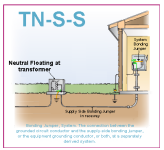
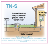
"S" - The grounded conductor and the equipment grounding conductor are provided as separate conductors.
"C" - The grounded conductor and equipment grounding function are combined in a single conductor.

The existing part of the prints @hhsting is reviewing is what I would call a 'TN-S-S' system.
EDIT: I suppose it might be more accurate to call it a TN-S-C-S system, as the neutral does provide part the protective (fault clearing) path
The permit applicant that has submitted plans to @hhsting is proposing to connect a new TN-S system (just phase conductors no neutral) to TN-S-S system, or at the transformer shown in the TN-S-S illustration.
The issue @hhsting noticed is the fault path from the proposed TN-S system (firepump) would be thru the system bonding jumper at the original building.
Here are some illustrations of the common systems we discuss here and how I would classify them in IEC terms.
 

Attachments

  • TN-S-S.png
    TN-S-S.png
    52.7 KB · Views: 9
  • TN-S.png
    TN-S.png
    55.5 KB · Views: 9
  • TN-C.png
    TN-C.png
    50.8 KB · Views: 9
Last edited:
I read threads like this and cant help but think the users of the NEC would benefit from understanding and following simple IEC style designations.
I really fail to understand how that would be helpful. The NEC tells us everything we need to know and I doubt that those who fail to understand the NEC would understand that.
 
I really fail to understand how that would be helpful. The NEC tells us everything we need to know and I doubt that those who fail to understand the NEC would understand that.
NEC is simple for most part. Service conductors the grounded conductor also bonds equipment. Non service conductors the bonding of equipment is via non current carrying conductor (the equipment grounding conductor).

Separately derived systems, are non service, but you generally have a choice of bonding the grounded conductor at the source or at the first disconnecting means

What else is there to know other than a few somewhat specific conditions where you can vary from what I just mentioned?

Especially after they eliminated conditions like bonding ranges/dryers to the grounded conductor or re-bonding grounding conductor at separate buildings (exceptions that allow existing to remain of course are still there)
 
I appreciate the feedback, its the over 1000V and DC stuff where I think the NEC would most benefit.
 
I appreciate the feedback, its the over 1000V and DC stuff where I think the NEC would most benefit.
The NEC does a very poor job with over 1000 volts and is working towards adding articles and rules for that, but they will be generic as most over 1000 volt systems are designed by engineers who don't really look at the rules in the NEC. The new over 1000 volt rules in the NEC will really be for very small jobs, like a single irrigation pump giving enough guidance for a code user to make a safe installation, and leaving the engineers to design the larger projects.
 
The NEC does a very poor job with over 1000 volts and is working towards adding articles and rules for that, but they will be generic as most over 1000 volt systems are designed by engineers who don't really look at the rules in the NEC. The new over 1000 volt rules in the NEC will really be for very small jobs, like a single irrigation pump giving enough guidance for a code user to make a safe installation, and leaving the engineers to design the larger projects.
I would love to see 1000+ volts supplying irrigation pumps from an installer perspective. Around here too many unqualified get their hands in this equipment, at very least after initial install, and is hard enough to trust them to do the right thing when nearly all of them have a 480 volt supply to them. Makes it worse when some are 480/277 wye and others are corner ground delta, or even single phase with phase conversion and even the irrigation equipment dealers and their technicians don't really understand differences between those systems.
 
Top