Nikola Tesla

Status
Not open for further replies.
Last week I caught the tail end of a documentary on one of those learning channels about Nikola Tesla and I learned some interesting things.

They said that AC was chosen over DC because the electrons did not have to flow all the way around the circuit and therefore less heat was created which meant smaller wires.

Now I always figured AC was chosen because the machine used to step it up and down was so reliable and had so few moving parts compared to its DC counterpart. So once Tesla invented the AC motor it was the logical choice. But I guess I was wrong.

They further explained that current was the flow of electrons.

Now that was not so surprising to me because I have heard that before. At the same time I have heard others dispute that. Notwithstanding the flow of charge when the charge is a known other thing like in a chemical fluid, do you agree or disagree that current is the flow of electrons?

Actually, I think it was in these fora that I first heard that current might not be the flow of electrons. And that started to make sense to me because if the voltage can travel faster than the speed of an electron then so too must the current. And with AC frequencies that have wavelengths that exceed the distance an electron can travel in the period of the wave the same thing becomes a problem to explain with flowing electrons.
 

zog

Senior Member
Location
Charlotte, NC
This has been discussed here before, with some interesting views. But, electrons do not really flow but rather transfer energy, think of a row of billiards balls in a line.
 

charlie b

Moderator
Staff member
Location
Lockport, IL
Occupation
Semi-Retired Electrical Engineer
Here is an explanation I wrote some time ago. I thought I had a second explanation of "drift velocity" or "electron drift," but I can't find it on my office computer. Perhaps it is on my home computer. Anyway, the short answer to your question is that current is charge in motion. Enjoy:
This is a long story, and I will give just a short version. Let me warn ?those in the know? that I wish to hear nothing whatsoever on the topic of ?drift current.? I know what it is, and indeed took a post-masters degree course on the topic. But I don?t want to confuse a new member of our profession, by getting too complicated too soon. Let us save that level of detail for another lesson, OK?

Current is ?charge in motion.? In our business, the things that actually move, and that carries its own charge with it, are electrons. As they move in one direction through a wire, the charge they carry can be detected traveling through the wire in that direction. For ?Direct Current? systems, the electrons are moving in one direction only. The amount of current, as measured in ?amps,? is determined by the amount of charge that passes by a given point during a given time interval. That is essentially the same as saying current is measured by counting the number of electrons passing by a given point in a given time interval.

For ?Alternating Current? systems, current will start off by having some small number of electrons moving in one direction along a wire. They start off at the source, travel to the load along the ?hot wire,? travel through the load, travel back to the source via the ?neutral wire,? and begin the cycle again. A few moments later, there are more electrons traveling in that circular path. A few moments later, there are still more. Some time later, there is a peak number of electrons moving in that circular path, and then the number keeps getting smaller. Eventually, the movement of electrons stops entirely.

Immediately thereafter, however, the electrons start moving again, but this time in the other direction. They start off at the source, but this time they travel to the load along the ?neutral wire.? Then they travel through the load, travel back to the source, this time via the ?hot wire,? and begin the cycle again. A few moments later, there are more electrons traveling in that circular path, a path that is opposite in direction to the initial path. The number of electrons moving in that path grows to a maximum, then becomes smaller, and eventually becomes zero. At that point, electrons start moving in the original direction once again.

The time it takes for this entire process to run, from zero current, to maximum current in one direction, to zero current, to maximum current in the other direction, to zero again, is one ?cycle.? In the US, our AC systems have 60 such cycles each second. In Europe, they have 50 such cycles in each second.


Besoeker

Senior Member
Location
UK
This has been discussed here before, with some interesting views. But, electrons do not really flow but rather transfer energy, think of a row of billiards balls in a line.
Yes. I agree.
For alternating current, they wiggle back and forth a bit. For 60Hz it's one way for a half cycle and back on the next half cycle. But a tiny bit really.
For 10A in a 2.5mm^2 copper conductor (about 10AWG) the movement back and forth is about 0.0001 of an inch according to my quick calcs.
Not a lot - and hardly what one would consider a flow.
 

dereckbc

Moderator
Staff member
Location
Plano, TX
Well for one thing AC has higher losses than DC because with AC not only do you have resistance losses in the wires transporting from point A to B, but you also have reactive impedance in addition. That is why we have High Voltage DC Transmission today.

However it really comes down to feasibility and economics. AC is extremely easy to regulate with simple inexpensive, robust devices (tough, and can take a licking and keep on ticking) like transformers. DC is extremely hard and expensive to distribute and regulate. For example take your home service. The POCO distributes at a high voltage like 13.2 KV. to get it down to something safe and usable like 240 in you home takes a very expensive electronic regulator which is very sensitive to transients like lightning.
 
Last edited:

SAC

Senior Member
Location
Massachusetts
They said that AC was chosen over DC because the electrons did not have to flow all the way around the circuit and therefore less heat was created which meant smaller wires.

This is incorrect, and you were pretty much correct in your later comment. The issue with DC was that there was no economical method to increase the generated voltage for transmission, and to step it back down for utilization. AC was easily stepped up to a high voltage for transmission and then back down for utilization, greatly reducing transmission loss and making long distance transmission much more economical for AC than for DC (imagine the cost if transmission was at 120v!). This is a fact that Edison fought quite viciously - so much so that he performed public electrocutions of animals using high voltage AC to show how it was inferior to low voltage DC. I also seem to recall that the AC generators and motors of the era (of Tesla's design) were more efficient than their DC counterparts. In the end economics won over fear tactics, and AC became the standard for electrical distribution worldwide.

Fast forward to now, and we have economical methods to step DC up and down, and we now have many high voltage DC transmission systems in use.
 

dereckbc

Moderator
Staff member
Location
Plano, TX
Fast forward to now, and we have economical methods to step DC up and down,
Not so sure I would use the term economical when compared to transformers. To step DC up or down efficiently requires a Switch Mode conversion of taking the DC at the input, convert it to high frequency AC, step the voltage up or down with a transformer, and then rectify back to DC again. Couple that with the fact solid state devices are sensitive to transients and leads to a high failure rate.
 

Besoeker

Senior Member
Location
UK
Not so sure I would use the term economical when compared to transformers. To step DC up or down efficiently requires a Switch Mode conversion of taking the DC at the input, convert it to high frequency AC, step the voltage up or down with a transformer, and then rectify back to DC again. Couple that with the fact solid state devices are sensitive to transients and leads to a high failure rate.
For high voltage transmission, usually in the hundreds of kV range, the AC is first rectified to produce the DC. At the receiving end, it usually uses a line commutated inverter. Something akin to a DC drive in regen mode. There is no intermediate high frequency with such a system.
 

Jraef

Moderator, OTD
Staff member
Location
San Francisco Bay Area, CA, USA
Occupation
Electrical Engineer
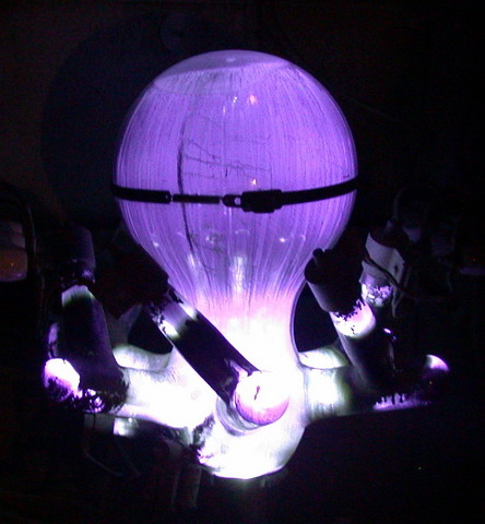
I have seen the Pacific Intertie System plants at both ends. In Celilo, the converter station on the Columbia River in Oregon, 230kVAC was converted to 500kVDC using giant mercury arc valves. They are bizarre looking things like something from a 1930's horror flick.
arcvalve.jpg

At Sylmar in Southern California, they used the same technology until it was destroyed in an earthquake, now they convert the 500kVDC back to 230kVAC using transformers fed by a 6 pulse thyristor based system built by ABB. It only works because of the economy of scale. Apparently in 2000 (after I saw it) BPA changed to a thyristor based system built by Siemens at Celilo too.

If Edison had his way back then, we would have had DC generating facilities every 20 or so miles and only the rich could afford electricity...
 

Besoeker

Senior Member
Location
UK
I have seen the Pacific Intertie System plants at both ends. In Celilo, the converter station on the Columbia River in Oregon, 230kVAC was converted to 500kVDC using giant mercury arc valves.
I have come across a mercury arc rectifiers. Mostly those that we replaced with thyristor rectifiers.

My late, great friend, Tommy, used to describe them as mercury archaic rectifiers. He had a way with words.
 

dereckbc

Moderator
Staff member
Location
Plano, TX
For high voltage transmission, usually in the hundreds of kV range, the AC is first rectified to produce the DC.
Bo thanks but I am familiar with HVDC transmission as i designed a couple of sub stations between TX and OK, and LA and TX. My comments was with respect to distribution.
 

K8MHZ

Senior Member
Location
Michigan. It's a beautiful peninsula, I've looked
Occupation
Electrician
I have seen the Pacific Intertie System plants at both ends. In Celilo, the converter station on the Columbia River in Oregon, 230kVAC was converted to 500kVDC using giant mercury arc valves. They are bizarre looking things like something from a 1930's horror flick.
arcvalve.jpg

At Sylmar in Southern California, they used the same technology until it was destroyed in an earthquake, now they convert the 500kVDC back to 230kVAC using transformers fed by a 6 pulse thyristor based system built by ABB. It only works because of the economy of scale. Apparently in 2000 (after I saw it) BPA changed to a thyristor based system built by Siemens at Celilo too.

If Edison had his way back then, we would have had DC generating facilities every 20 or so miles and only the rich could afford electricity...

Great pic!

I saw some pics of old time merc rectifiers used on a smaller scale and they were awesome! The pic showed the glass and the arc, a six pole rectifier and it was like a small part of the sun was in there, except it was blue.

I can't imagine what the glass in the pics you posted hold hostage. I'll bet seeing one in action would be breathtaking.
 

Jraef

Moderator, OTD
Staff member
Location
San Francisco Bay Area, CA, USA
Occupation
Electrical Engineer
It was. Your hair stands on end. Noisy too, like a gazillion bees. I was working on an 800A rotary UPS they had just for the breaker control system. Imagine needing 800A of capacity just for breaker control power...
 

dbuckley

Senior Member
I think there is just one mercury arc valve HVDC link left in the world; Here in NZ our HVDC merury arc installation shut down last year, and I seem to recall it was the second to last old school station.

Traditional HVDC links do rel;y very much on economies of scale, as the converter stations cost an arm, a leg, and your firstborn, and take up a lot of real estate, however there is now HVDC 'lite' which uses IGBTs rather than thyristors, and addresses the smaller scale marketplace. Still not cheap, though, compared to a couple of transformers...
 

Besoeker

Senior Member
Location
UK
Bo thanks but I am familiar with HVDC transmission as i designed a couple of sub stations between TX and OK, and LA and TX. My comments was with respect to distribution.
You mentioned Switch Mode conversion.
I didn't think switch mode techniques were used on DC distribution.
As far as I was aware it was mostly line-commutated conversion and inversion.
 

swei

Member
Well for one thing AC has higher losses than DC because with AC not only do you have resistance losses in the wires transporting from point A to B, but you also have reactive impedance in addition. That is why we have High Voltage DC Transmission today.

That and the fact that a DC line will carry quite a bit more power at a given peak (insulation) voltage.
 

dbuckley

Senior Member
One of my pastimes is showing movies in the local hall on a Saturday night. We've got some projection equipment that dates back a few decades, but still does the business.

We also have an ancient slide projector, not used for many years, that also has a carbon arc lightsource, which has an old rectifier to supply it, pictured below with the doors open:

mercarc_500x375.jpg


You just gotta love mercurty arc rectifiers; they are gorgeous. We have three of these units, so I suppose I could actually make this one work properly...
 
Status
Not open for further replies.
Top