StreamlineGT
Senior Member
I put a GE 200 amp panel with the generator interlock bracket, and he is wondering if there is a way to install some sort of indicator (light) to indicate when normal power has been restored.
For those of you unfamiliar with the setup..
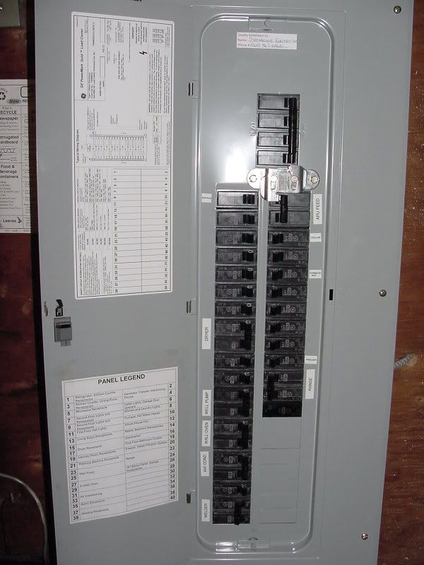
For those of you unfamiliar with the setup..
")

