One Generator Feeding 2 buildings......(one more round)

Status
Not open for further replies.

Otis2011

Member
Location
Maumee, Ohio
I have been investigating the case of 3 Pole automatic transfer switches, single generator, and two 3P/4W buildings with dedicated LV transformers. I have come to the conclusion it is impossible to discuss without a one line sketch. See attached.

I have laboriously studied the 28 previous posts on the subject. Hoping to get some good clarification on the issue.

Basic question, is the proposed system one-line Code, not code (state 2011 NEC references with thoughts), an AHJ decision, other?

Thanks in advance.
 

Attachments

  • 3Pole_ATS_2Building_scan.pdf
    43.7 KB · Views: 14
The one thing I see is the ATS's . You would need 4 pole transfer switches to switch the neutral because of your GFP.
 
Yeah, I would recommend 4 pole ATS's, as well. You can't tie the neutral and ground together at the generator if you're using 3 pole switches, because it's not a separately derived system.

Also, if you do go the 4 pole route, you'll need a ground rod at the generator (or building steel, etc.).
 
Ground fault paths

Ground fault paths

If my system grounding connection is at the 400 amp breakers, outside, ahead of the main distribution panels, it appears there are not multiple ground fault paths. See my mark-ups showing ground fault return paths. Am I missing something? That why I'm asking this knowledge base.

The reason for the 3 pole push is that they are available to the project.

Thanks.
 

Attachments

  • GF paths.pdf
    91 KB · Views: 9
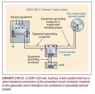
I don't think you can make this system Code-compliant if you use 3-pole switches. See 250.30, and Exhibits 250.12 and 250.13 in the NEC Handbook.
 
I don't think you can make this system Code-compliant if you use 3-pole switches. See 250.30, and Exhibits 250.12 and 250.13 in the NEC Handbook.


In your drawing you are showing the N-G bonded in the generator and in the main disconnects. If you wire it the way you propose and the GFP did not go out on nuisance tripping you cannot rebond the N-G in the generator. You would have to run 5 wire back to the ATS's. Unbond the N-G and have it as a non-separately derived system.

I still think you will need to install the generator as a separately derived system and switch the neutrals because of the GFP.
 
Cummins application reference

Cummins application reference

IWIRE,

Thanks for taking an interest. Attached is a section of the Cummins Transfer Switch application manual (issue 3) that originated my question. My exact situation is Case 3 and Figure 31 (attached). The entire document can be found searching "Cummins A048F226".

The paper states in the case 3 discussion that "switched neutral transfer (4 pole) should be used" .......but does not state 3 pole is used is a code violation.

The paper also states the generator is a separately derived source in this arrangement, but shows no connection between N and G at the generator. This paper is dated 3-2014. I have an older version that does show a connection between N and G to cloud the issue further. Figures 31 and 32 in latest release were figures 30 and 31 in previous editions. Note the typo in last paragraph, "same as Figure 30" should be "same as Figure 31".

The material also states that GFP will work properly. (I believe this is due to the large difference in impedances between the two paths. In my case, the local path is 40 feet, and the parallel path through the second service is 1000 feet. At least a ratio of 15:1).

Ground fault protection is not required in my application (400 amps; 208 volts). It is an "optional standby system".

I am looking for discussion of if the arrangement shown in Figure 31can be installed. Is it an AHJ decision?

Thanks
 

Attachments

  • Cummins_Fig31.pdf
    126.1 KB · Views: 11
I don't see how the Figure 31 generator is a separately derived system. The neutral and ground are not connected at the generator, so it is not separately derived.

nsd_zps328ee041.jpg


With two utility sources, it's probably legal to have it set up the way it's shown in Figure 31, but with the neutral and ground bonded in two places, I don't see how that doesn't create parallel paths.

And if you're not going to use GFP on the mains, it could be a problem down the line.
 
Pharon,

Attached is the figure in the earlier version of the ATS manual. The text describing the figures has not changed other than the renumbering of the figures. Note the bonding of the N and G at the generator.

I agree parallel paths are made, but due to large differences in the path lengths, 1000 feet in my case, The GFP will see 95% of the fault current. I believe this is why the statement "GFP sensors will work properly" is made in the text describing the figure. In my case, path 1 is 40 feet of #2/0. Path 2 is 500 feet of #2/0 plus 500 feet of 500 mcm.

Note the figure does not show the ECG bonded to the generator. Is this implying 250.142 (A) (3), "Use of grounded circuit conductor for grounding equipment" ? The early figure shows the neutral bonded to case ground, but does not indicate an earth ground (GEC).

In the earlier figures 27 and 29, where the multiple ground fault paths labeled "improperly installed", the path lengths are comparable in length (impedance), the main GFP would only see 50% of the fault current.

Thoughts?
 

Attachments

  • Old Figure 30.pdf
    67.1 KB · Views: 6
When it comes to generators, you either have a separately derived system -- where you're bonding the neutral and ground at the generator and switching the neutral at the ATS, or a non-separately derived system -- where you're bringing both the neutral and ground from the generator back to the main disconnect and bonding them only there, and not switching the neutral.

With two different main disconnects, you can't bond in only one place, and I think this will lead to parallel grounding problems, even if it's not strictly a Code violation. It still may be, but I am unable to cite Code that would expressly prohibit it.

If it were me, I would use 4 pole switches and make it a separately derived system. It's the safest and most stable solution.

If you insist on using 3 pole switches, then make sure that you do not connect the neutral and ground at the generator -- bring them both back to the main disconnects and bond them only there. I would also provide ground fault protection on the main disconnects if I were forced into this scenario.
 
Status
Not open for further replies.
Top