Parallel conductors

Question, in the attached picture, you will see that the parallel conductors have a fuse in each conductor, the other end terminates with both wires of the phase on one terminal, is this a good practice? I'm thinking that if a fuse would blow than the other conductor would have to carry the entire load? I have never seen parallel conductors installed in this manor before! What do you all think?
 

Attachments

  • parrell conductors.jpg
    parrell conductors.jpg
    1,015.1 KB · Views: 35
I don't see the issue. Think of a large water heater where the loads are sub divided. It really isn't different. Those wires on the load side are not parallel conductors but they are using the tap rule.
 
My concern is if you blew 1 fuse on the same phase what then? Huge phase imbalance? Loss of 50% of the conductor? Weird voltage imbalances? It looks OEM but I'm just wondering why would OEM wire it that way? Seems odd.
 
i know it doesn't look that way but they terminate on the same point on the other end
Here is the definition of parallel
conductors shall be permitted to be connected in parallel (electrically joined at both ends) only in sizes 1/0 AWG and larger

The load side of the breaker shown is not a parallel connection. Sure the have 2 wires coming off each phase but they split at the other end. They are not electrically joined at both ends.
 
IMHO we have to distinguish the NEC definition of 'parallel conductors' from other forms of parallel.

The conductors are not 'parallel' per the NEC strict definition of 'parallel conductors' specifically because they don't go from one solid electrical connection to another. The NEC definition is pretty much about a 'wire' formed from smaller wires, and if some device interrupts the smaller wires than you don't have a 'parallel conductor'.

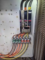
But they are clearly electrically in parallel. Current flows from the breaker lug, splits to take one of 2 paths, goes through the fuses and then the wire, and joins back up at the next lug. It then goes through the load, splits because you have 3 phases, hits the next load lug, splits to take one of 2 paths, goes through the fuses, and then ends up on a breaker lug.

Is this a good practice? I don't know. It looks very much akin to 'cable limiters' or 'limiting lugs' that are intended to isolate parallel segments in the event of short circuit; but those are ordinary fuses that would blow on overload or short circuit. The breaker is an 800A breaker, the fuses are 150A fuses.... If you had a 400A overload on that setup I'd expect one fuse to blow and the second one to follow quickly.
 
Top