parallel wire ampacity

Status
Not open for further replies.
Where can i find a good formula for what amperage each wire will carry if you are doing parallel feeder runs?

I found a formula in (Electrical Wiring Commercial) but just by looking at it, i can tell that it is wrong.

In the (Electrical Wiring Commercial), they gave this problem.

A 1600 ampere service consists of four conduits, each containing four 600 kcmil Type THWN copper conductors. The allowable ampacity of this conductor is 420 amperes. When the service is operating at 1600 ampere, what is the current in each of four parallel sets of conductors, if their lengths are 20 ft., 21 ft, 22 ft, 23 ft?


Books solution--- (length of wire / length of wires combined) x Amps

total length = 20 + 21 + 22 + 23 = 86 ft

The current in each set is inversely proportional to the resistance, which is proportional to the conductor's length. The proportional resistance of each set is
(20/86) x 1600 = 372.09 A
(21/86) x 1600 = 390.6 A
(22/86) x 1600 = 409.3 A
(23/86) x 1600 = 427.9 A

Since current is inversely proportional to resistance, the currents would be 428, 409, 390, and 372.

To me, above formula doesn't look correct because it's missing some factors. Try out theses wire lengths. 1 ft. 21 ft. 22 ft. and 23 ft.

(1/67) x 1600 = 23.88 A
(21/67) x 1600 = 501.5 A
(22/67) x 1600 = 525.4 A
(23/67) x 1600 = 549.25 A

See one wire carries 24 A and all the other carry 500+ amps. It's wrong.

Some other factors that the formula is missing out.

If a short wire carries more amperage, it heats up which means the resistance goes, which then makes the amperage go down. The longer wires stay cool because they carry less amperage which gives them less resistance so then they start to carry more amperage when the shorter wire heats up.


If any one has a good formula that includes all the factors please i would like to have it. I would really appreciate it.
 
Last edited:
For parallel sets of wire, the NEC normally requires each set to be the same lenght, and have the same characteristics. So normally, each set would be the same length. I can't imagine any case where you would have one set that is 0.1 ft long, and one set that is 23 feet long. There just isn't any reason to do that, and it would be a code violation.

Second, I'm not sure that formula is wrong. Sure, it ignores changes in wire temp., but that doesn't make it wrong. For one wire 20 times shorter than another, it makes sense that the shorter wire would carry 20 times the current.

Draw the circuit out, using the wire resistances, and use what you have learned about circuit analysis to solve for the currents through each wire.

Also, I think the example in the book was meant to show why you need to keep parallel sets of wire the same length.

Finally, you should be able to find a formula for wire resistance vs. temp., and use what you know about circuit analysis to find the formula you want.

Steve
 
steve066 said:
Second, I'm not sure that formula is wrong. Sure, it ignores changes in wire temp., but that doesn't make it wrong. For one wire 20 times shorter than another, it makes sense that the shorter wire would carry 20 times the current.


Steve


According to the calculation in the OP the shorter conductors carry less current. So either you're incorrect or the information from the book is incorrect.

The current in each set is inversely proportional to the resistance, which is proportional to the conductor's length. The proportional resistance of each set is
(20/86) x 1600 = 372.09 A {20 feet}
(21/86) x 1600 = 390.6 A {21 feet}
(22/86) x 1600 = 409.3 A {22 feet}
(23/86) x 1600 = 427.9 A {23 feet}
 
Still not sure. For example, it doesn't specifically say that the formula for 20/86 is for the 20 foot conductor. In fact, in the last line, he lists the answers in reverse order. So the highest current might be for the shortest conductor.
 
I took the problem out of the book word by word. You right about that in the book they wrote it is inversely proportional to resistance, so they flipped the amperages and gave shortest wire the most amperage.

But if you do the same thing with the wire lengths i was trying to do 1 ft. 21 ft 22 ft. and 23 ft. The flip method would make no sens because there will be one short wire and three large amperages.
 
I see what you are saying. You get three high currents, and one low current.

You should get one high current, and 3 lower currents.
Steve
 
This is basically a current divider. Try using the formula shown here (in the top right diagram):

http://en.wikipedia.org/wiki/Current_divider

Edit:

I get about 1407 amps for the 1 foot wire, and about 72 amps for the 21' wire.

The formula you posted is apparently an approximation, and only valid when the wire lengths are all similar.

Steve
 
Last edited:
The method used in the book is only an approximation and it works well for that purpose when the lengths are close as required by the code rules. It does not work with a large difference as you have found out. If you assign a resistance of 1 ohm per foot of wire, solve for the total resistance, the voltage drop of the parallel sets, and then the current of each of the conductors in the parallel set, you will get much more reasonable numbers. 1408A on the 1', 67A on the 21', 64A on the 22' and 61A on the 21'.
Yes, both of these methods ignore the the change in resistance as a result of the temperature change, but for a code compliant installation that change is not really significant.
Don
 
parallel wire ampacity

The textbook current sharing only sort-of-works if the wires stay at the same temperature, which they won't.

I once had to put two 10 A relay contacts in parallel to carry close to 20 A. The contacts kept burning out, so I measured the contact resistance of the closed contacts using a four-terminal (Kelvin) method and put each contact in series with a few inches of #26 wire (= a homemade resistor of ~ 1/40 ohm) that had 5x or 10x the resistance of the closed contacts. So there were two series circuits in parallel, each series circuit consisting of closed contacts and a short piece of wire.
The contacts held, but this kind of current sharing is impractical for heavy conductors.

Trying to measure this in the lab will probably make you crazy because the ammeter shunts probably have more resistance than the wires you are measuring. Maybe NIST has the equipment to do this accurately.
 
I did it a little different than Don but came up with the same answer.

I set the shortest length (20) to 1.

Then I divided the other lengths by the shortest to determine what % of the shortest length they are:

20/20 = 1
21/20 = 1.05
22/20 = 1.1
23/20 = 1.15

Then take the inverse of these numbers to get the resistance as referenced to the shortest conductor:

1/1 = 1
1/1.05 = 0.9524 (or 95.24% of the 20' length)
1/1.1 = 0.9091 (or 90.91% of the 20' length)
1/1.15 = 0.8696 (or 86.96% of the 20' length)

Add up the inverses:
1+.9524+.9091+.8696 = 3.731

1600 Amps / 3.731 = 428.8 (this is what the 20' length carries).
21' length carries 428.8 x .9524 = 408.4
22' length carries 428.8 x .9091 = 389.8
23' length carries 428.8 x .8696 = 372.9


It may be clear as mud, but it works for me. :)
 
hardworkingstiff said:
It may be clear as mud, but it works for me. :)
How about something a little clearer :grin:

Take your lengths and add up their reciprocals
1/20 + 1/21 + 1/22 + 1/23 = 0.186​
Now multiply the total current by reciprocal of the length then divide by the result above.
1600 ? 1/20 ? 0.186 = 429 A
1600 ? 1/21 ? 0.186 = 408 A
1600 ? 1/22 ? 0.186 = 390 A
1600 ? 1/23 ? 0.186 = 373 A​


If you apply this to set with 1' in place of the 20' conductor:
1/1 + 1/21 + 1/22 + 1/23 = 1.14​
Then:
1600 ? 1/1 ? 1.14 = 1407 A
1600 ? 1/21 ? 1.14 = 67.0 A
1600 ? 1/22 ? 1.14 = 64.0 A
1600 ? 1/23 ? 1.14 = 61.2 A​
 
Smart $ said:
How about something a little clearer :grin:
I had started writing up a reply to the effect that all methods given so far are inaccurate. But I took a little extra time to work out what the "real" method would give as the "correct answer." After expending two or three sheets of scratch paper, I did verify that Smart $'s method (from post #11) does give the correct answer. So if you find that process "a little clearer," feel free to use it (you have my permission ;) :grin: ).

Please note, however, that I only verified that process works for a set of four parallel resistors. As a homework assignment, your job is to use the method of Mathematical Induction to prove that it works for any number of parallel resistors. :smile:
 
parallel wire ampacity

A formula, you want?

At least two of the factors that go into that formula:
Copper wire resistance increases +0.39% per degree celsius (the temperature coefficient of copper).
The conductor temperature rise above ambient is proportional to the current squared.

There may be no "closed-form" solution to this, so you'd have to zero in on the answer, just as X = 1 + 1/X has no closed form answer for X.

I'd plug all this into a spreadsheet along with your conductor resistance at 25degrees and adjust the numbers for your circuit until all conditions are simultaneously satisified. Or, you could also write a computer program that iterates until you get within your desired accuracy.

Worst case outcome? The temperature of each wire (and its resistance and therefore its current) oscillates around some unknown equilibrium point, and depending on the "Q" of the system, it takes a long time to stabilize. If this happens, the computer program you wrote may "hang."

I need a drink.
 
charlie b said:
...As a homework assignment, your job is to use the method of Mathematical Induction to prove that it works for any number of parallel resistors. :smile:
Ummm... I do hope this statement is directed at the OP :D

FWIW, I have already proven it (to myself). I have even made an Excel calculator for up to 12 parallel conductors.
 
Smart $ said:
FWIW, I have already proven it (to myself). I have even made an Excel calculator for up to 12 parallel conductors.
Proven it how, if I may ask? There are only two types of proof that are valid. One is to do the algebraic manipulations associated with resistors in parallel. That is how I proved your formula works for four resistors. The other way is Mathematical Induction, and it would prove the formula works for any number of resistors.

For those interested and not yet too bored :roll: , Mathematical Induction is a two-step process. First, you prove it works once. Next, you prove that if it works one time, it will also work the next time. You infer from this that it will always work.
 
charlie b said:

Proven it how, if I may ask? There are only two types of proof that are valid. One is to do the algebraic manipulations associated with resistors in parallel. That is how I proved your formula works for four resistors. The other way is Mathematical Induction, and it would prove the formula works for any number of resistors.
Been there, done that... not doing it again. I feel 100% confident in my proof. If you don't, feel free to do it yourself ;)

FWIW... The Excel file
 
charlie b said:
Proven it how, if I may ask? There are only two types of proof that are valid. One is to do the algebraic manipulations associated with resistors in parallel. That is how I proved your formula works for four resistors. The other way is Mathematical Induction, and it would prove the formula works for any number of resistors.

For those interested and not yet too bored :roll: , Mathematical Induction is a two-step process. First, you prove it works once. Next, you prove that if it works one time, it will also work the next time. You infer from this that it will always work.

Charlie:

Its really just a simple current divider, like I posted earlier. I know Wikiapedia leaves something to be desired as a reference, but the current divider formula is pretty well known. Very similar to the voltage divider.

Steve
 
steve66 said:
It?s really just a simple current divider, like I posted earlier.
I know that. My first method, the ?algebraic manipulations associated with resistors in parallel,? is the current divider problem. But if you have more than two resistors to deal with, the algebra gets a bit more detailed. With four resistors, it is quite a collection of "1/this" and "1/that" terms.
 
charlie b said:

I know that. My first method, the “algebraic manipulations associated with resistors in parallel,” is the current divider problem. But if you have more than two resistors to deal with, the algebra gets a bit more detailed. With four resistors, it is quite a collection of "1/this" and "1/that" terms.
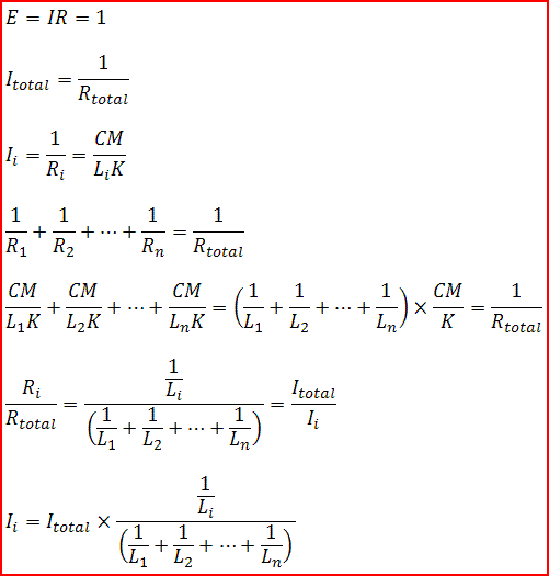
Charlie,

I believe I based my algebraic proof on ratios. Went something like this regarding the math part...

algebraic1.gif
 
Last edited:
Status
Not open for further replies.
Top