Phase shift

Status
Not open for further replies.

egorblack

Member
Location
California
Service_new.jpg

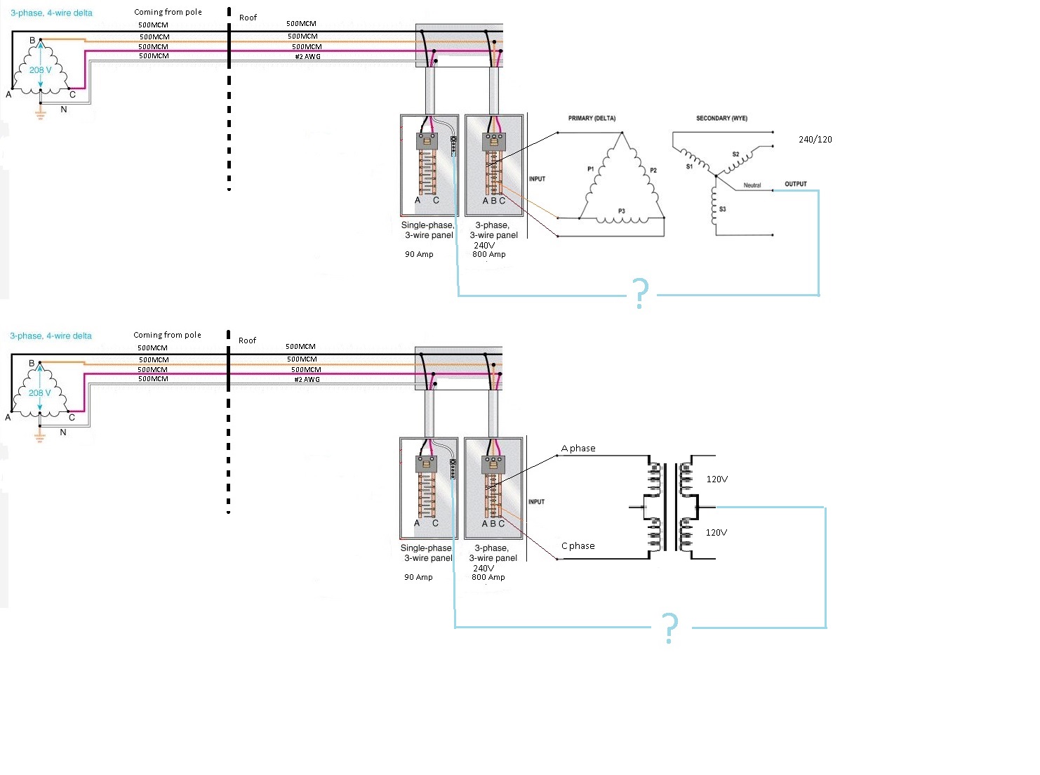
Hello. Basically, need a bigger neutral in the building. I have only #2 neutral wire coming into the building. And I can not get a bigger neutral wire from utility company, because I will need to upgrade my 800Amp panel, so I am trying to create a new neutral myself.
As I understand, in the top schematic I will have voltage between neutrals because of phase shift in transformer(correct me if I am wrong).
Can somebody tell me if I can connect neutrals in bottom drawing?
 
I’m not sure I understand. You can’t get a new bigger neutral from the utility?
they gave you a 500MCM.
how much bigger you want?
 
In a grounded system, the neutral is most often selected to be the grounded conductor.
In both of your diagrams it is possible to ground both the left (utility) side neutral and the right (derived) side neutral.
If in addition to both bring independently connected to the Ground Electrode System (GES) they are directly connected to each other, then you have a non separately derived system (non-SDS).
If they are only at the same voltage by virtue of their GES connection, then the right side is a Separately Derived System +SDS).
The issue is not that the neutrals are different in phase or voltage. It is that the voltage to ground of the A, B and C lines is different between the left and right side. But there is no reason to want to interconnect them!

Sent from my XT1585 using Tapatalk
 
It appears you basically setting an isolation transformer with the same voltage in, same voltage out? On the first diagram, you should be getting 120/208 on the output, not 12/240 or your neutral to phase voltage would be high, which is not what you want. Otherwise, yes, you can get a larger neutral from that seperate system because the service will not see any increase on its neutral load. Trying to avoid pulling a bigger neutral in the exsisting service?
 
egorblack, your question seems confused.

It sounds like you have a situation where your service neutral capacity is lower than what your load requires, and you want to use a transformer to 'support' the neutral. In other words you want to use the same phase conductors supplied by the service, but use a transformer somehow in parallel with the service neutral to reduce its load.

The critical point implied by your question is that both the neutral and the phase terminals of the transformer are connected to your service conductors. You can always connect _one_ and only _one_ of your transformer secondary terminals to your primary circuit; with only one terminal connected you don't have a complete circuit and thus 'phase angle' doesn't matter at all. In fact, the most common way of connecting transformers requires 'grounding' the neutral of the secondary, and since all grounds are connected together this implies that the secondary neutral _is_ connected to the primary neutral (or primary grounded conductor).

In theory this is possible with a suitably matched auto-transformer connected to both the primary phases and the primary neutral. In practice this is _not_ permitted under the NEC, and not really feasible in any case. The most likely result is that you will see the transformer injecting current onto the neutral if there is any phase voltage imbalance, making your actual situation worse.

However you can achieve the same result by following the common practice of using a normal transformer in the normal fashion to create a 'separately derived system'. You would supply a standard delta-wye (or delta-delta) transformer to create (at your preference) a 208/120V wye system, or a 240/120V high leg delta system, and then use that transformer to supply your line-neutral loads. You would _not_ support the primary neutral. Instead you would create a complete new system with its own neutral and its own separate phase conductors. Line-neutral loads would be supplied by the derived phase to derived neutral terminals, with _no_ neutral current added to the service neutral.

-Jon
Auto transformer would not help, it would only raise or lower the existing voltage, which would only lower neutral current by a small amount. What he/she is wanting to do will work because any unbalanced current (neutral) is confined to the transformer. It will translate to phase to phase current instead of phase to neutral on the service side.
 
Auto transformer would not help, it would only raise or lower the existing voltage, which would only lower neutral current by a small amount. What he/she is wanting to do will work because any unbalanced current (neutral) is confined to the transformer. It will translate to phase to phase current instead of phase to neutral on the service side.

You are exactly correct for normal installation practices. I was reading between the lines because of the way he asked his question, worried about the voltage difference between the transformer secondary neutral and the primary neutral. I guess I didn't do a very good job of making that clear.

(repeating for the benefit of the op) With a normally installed transformer the secondary terminals are completely isolated from the primary. You then (generally) ground the secondary neutral, but you don't connect any other terminals from secondary to primary, so no current flows from secondary to primary. There is no voltage difference between secondary neutral and primary neutral because the _single_ secondary grounding connection is what _defines_ the secondary neutral voltage. Phase current doesn't come from your service, it comes from this transformer. Neutral load current doesn't return on your service, it goes back to this transformer. Power used on the secondary shows up as power supplied by the primary phase conductors, with no primary neutral current.

The only situation in which you are worried about the difference between secondary neutral and primary neutral voltage is in an autotransformer situation, and this is not limited to 'buck/boost' transformers. A 'zig-zag grounding transformer' is a type of autotransformer used to derive a neutral point for an ungrounded delta. If you had a grounded wye service, and connected a zig-zag grounding transformer, then in theory the zig-zag derived neutral would be at the same voltage as the supply neutral, and you could connect the two, and the zig-zag transformer would 'support' the neutral. In practice this would be a horrible installation; with the zig-zag transformer injecting current into the neutral trying to compensate for any phase imbalance.
After looking at it again, I see what you are saying, also I was assuming he was adding panels on the output of the transformers, but that does not look to be the case.
 
[U]GoldDigger,[/U] based on These, Delta-wye transformers introduce a 30, 150, 270 or 330 degree phase shift, so I think it will be voltage between old and new neutrals.

[U]hillbilly1[/U] Yes, my 800Amp panel does non have a neutral, so I am creating a new one, but whole building is grounded by "old" or existing neutral. I am just afraid that it will have voltage between old and new neutrals, so when I connect them together I will get a big BOOM.


[U]winnie[/U], can you, please refer to any literature explaining what you have said about neutrals?
I think that because old neutral comes from the middle of the coil of the outside transformer, and new one comes from common connection point of coils.

[U]hillbilly1[/U] Yes, I will install panels on the new transformer output, what difference does it make?
can you, please, analyze bottom schematic? I think I have more chances on that one. Thank you.
 
Regardless of the phase shift introduced by the transformer, there will be no difference in the neutral to ground voltages, since that voltage is zero. There may be a phase shift in the (probably non-zero) neutral current.
But that is no reason not to connect the neutrals.

Sent from my XT1585 using Tapatalk
 
[U]winnie[/U], can you, please refer to any literature explaining what you have said about neutrals?
I think that because old neutral comes from the middle of the coil of the outside transformer, and new one comes from common connection point of coils.

What do you think?

Voltage must be measured between two different points. If those points are not part of a circuit then the voltage will be very poorly defined by various leakage currents, static charges, capacitive coupling, etc.

For literature just look up transformer connection diagrams.

Jon
 
based on These, Delta-wye transformers introduce a 30, 150, 270 or 330 degree phase shift, so I think it will be voltage between old and new neutrals.

displacement won’t make a difference. We connect Dy1 and Dy11 neutrals together everyday.
 
[U]hillbilly1[/U] Yes, my 800Amp panel does non have a neutral, so I am creating a new one, but whole building is grounded by "old" or existing neutral. I am just afraid that it will have voltage between old and new neutrals, so when I connect them together I will get a big BOOM.

[U]hillbilly1[/U] Yes, I will install panels on the new transformer output, what difference does it make?
can you, please, analyze bottom schematic? I think I have more chances on that one. Thank you.
[/QUOTE]

You will not have any voltage difference between the neutrals if you properly bond XO. It will not go boom boom. If you do not properly bond XO, you will have ghost voltages between the two different neutrals, but it still will not go boom boo
m! Your ground is also your neutral on the service side, it is just undersized,
 
Last edited:
Service_new.jpg

Hello. Basically, need a bigger neutral in the building. I have only #2 neutral wire coming into the building. And I can not get a bigger neutral wire from utility company, because I will need to upgrade my 800Amp panel, so I am trying to create a new neutral myself.
As I understand, in the top schematic I will have voltage between neutrals because of phase shift in transformer(correct me if I am wrong).
Can somebody tell me if I can connect neutrals in bottom drawing?
Both situations you are creating a separately derived system. Your jumper to the single phase panel neutral bus does nothing but create a ground reference for your separately derived neutral conductor in both cases. This is done all the time with SDS's.

If you are wanting to be able to utilize more 120 volt loads, the first one is able to utilize all three phases, but how practical that is may depend on utility source as well. If they have open delta source you may not have same capacity on all three supply lines.
 
[U]kwired[/U] I assume we have Closed Delta, as we have 3 transformers on the pole. On Open Delta it is usually two transformers on the power pole.
Thank you, guys, for helping. I will see which transformer is easier to find, and will let you know how it went.
 
Status
Not open for further replies.
Top