Ok so I get the concept of equally distributing the electrical stress and that shielding does that. BUT I'm still unclear what is happening to the volts per mil if we unshield. Is it going up? Is the electrical stress going up despite the volts/mil remaining the same? Walk with me thru my thought process here and tell me where I am going wrong:
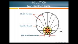
Take our hypothetical 15kv shielded conductor with 175 mil insulation, so 86 volts/mil. No let's unshield it and bring a grounded point object, or unequal proximity to a grounded object like in picture number one. Intuitively it makes sense that we have a concentration of electrical stress but the potential is still 15kv so there is still 86 volts/mil there right? So what's going on?
I’m going to take a stab at it.
In a MV cable the voltages are such that you have to protect the insulation from what it’s insulating.
let’s look at a cable.
There is the conductor, like any other conductor there are air voids. Next is a semi conductive layer (the black carbon containing layer next to the conductor), then the insulation. XLPE is somewhere around 600-800 volts per mil.
Then there is another semiconductive layer (black semi-con) over the insulation, then the copper tape or concentric neutral cable.
With these voltages the air dielectric will break down (50-70 volts per mil for air) with corona discharges.
This creates Nitric acid, UV light, and some heat.
This breaks down the insulation, leading to “treeing” which causes blowouts.
The first black semiconductive layer around the conductor itself basically provides an equal potential area within the actual conductors themselves. There is no real good place for the voltage to go when it’s wrapped within this first cocoon. No corona, or partial discharge, no insulation degradation.
the insulation itself does its job at its Volt per mil
Level, then the semiconductive layer on the outside does basically the same thing with the ground, returning fault currents.
you ever see a Tesla ball? Ever run your hand over it and see what happens with all the “sparks”?
They concentrate where your finger is located and “follow” it.
In your scenario, think of your unshielded cable as a Tesla ball with little sparks going everywhere. When you bring the grounded object closer you concentrate the corona discharge.
with the ball, it’s no big deal and cool to watch. With MV cable, it’s detrimental to the cable.