I respect all the contributers to the NEC Handbook and purchase one every couple publications.There are tons of information you don't get from the regular code book. No ones perfect and there are mistakes in about everything.
And when I find something that doesn't appear correct I like to confirm if I am wrong or right.
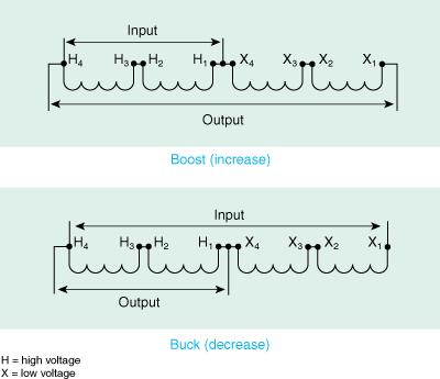
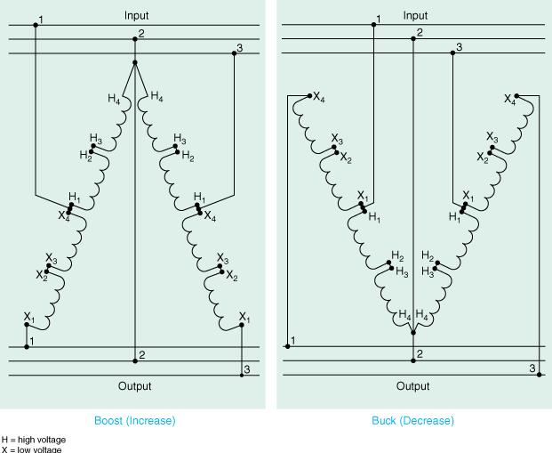
Please look at page no.80 Art. 210 Branch circuits of the 2002 hand book at the exhibits 210.8 and 210.19.
When we use the term buck in electrical terminology isn't it to apply a voltage to another voltage in opposite polarity to reduce it? In other words if I have a simple circuit with a 6 volt battery and insert a 1.5 volt battery in this circuit back wards wouldn't this reduce the voltage to 10.5 volts? And this is the true definition of the term buck.
Note exhibit 210.18 top left of page 80.
My problem with this circuit is not that we will no have a decrease or increase in the voltage because it will, but the way it is obtained.
I don't have a problem with the way it is done I would prefer it this way, but the definition is wrong.The definition of bucking.
This is a autotransformer in the boosting and reducing the boosting is correct but the bucking isn't bucking.To buck or decrease the voltage by bucking you would leave the wiring or taps as the boosting and just reverse the x or low windings polarity x1 and x4 would be reversed.
If you will examine the bottom exhibit you will notice it is correct to boost 1 and 4 between H and X need to connect and to buck 1 and 1 between H and X need to connect.
If I am wrong please explain.")
And when I find something that doesn't appear correct I like to confirm if I am wrong or right.
Please look at page no.80 Art. 210 Branch circuits of the 2002 hand book at the exhibits 210.8 and 210.19.
When we use the term buck in electrical terminology isn't it to apply a voltage to another voltage in opposite polarity to reduce it? In other words if I have a simple circuit with a 6 volt battery and insert a 1.5 volt battery in this circuit back wards wouldn't this reduce the voltage to 10.5 volts? And this is the true definition of the term buck.
Note exhibit 210.18 top left of page 80.
My problem with this circuit is not that we will no have a decrease or increase in the voltage because it will, but the way it is obtained.
I don't have a problem with the way it is done I would prefer it this way, but the definition is wrong.The definition of bucking.
This is a autotransformer in the boosting and reducing the boosting is correct but the bucking isn't bucking.To buck or decrease the voltage by bucking you would leave the wiring or taps as the boosting and just reverse the x or low windings polarity x1 and x4 would be reversed.
If you will examine the bottom exhibit you will notice it is correct to boost 1 and 4 between H and X need to connect and to buck 1 and 1 between H and X need to connect.
If I am wrong please explain.