lando_278
Member
- Location
- Hutchinson, Kansas, United States
I have a code question that I've been struggling with for the last few weeks. We are designing a skid package that is supposed to be a complete boiler room. Part of the requirement was to provide a single power drop for easy connection in the field.
We designed a power distribution system to provide 460 3 phase and 240/120 single phase. Originally we were going to use a Square D 10KVA dry type transformer for the single phase side. However, it could only be purchased in 3R and we needed everything NEMA 4. So we decided to stick it inside a panel from our UL508A panel shop.
I am a little worried & confused now on how this grounding system is supposed to be connected. I was previously referencing NEC 250.20-30. Which deal with separately derived systems and how to properly ground a power transformer with SBJ, EGC, GEC etc.
However, the unit came wired from the panel shop with the incoming EGC connected to panel chassis and the transformer neutral/120vac bonded back as well. With no reference to a connection for a GEC. I am wondering if, since this is a UL panel, the NEC code even applies to this situation. Do I need to isolate my transformer neutral from the enclosure chassis and provide a GEC/Earth Gnd?
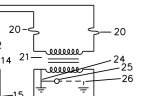
I've shared the preliminary drawings for this panel. Please provide any feedback. I have typically been a control systems engineer so this is stepping beyond the bounds of my familiarity.
We designed a power distribution system to provide 460 3 phase and 240/120 single phase. Originally we were going to use a Square D 10KVA dry type transformer for the single phase side. However, it could only be purchased in 3R and we needed everything NEMA 4. So we decided to stick it inside a panel from our UL508A panel shop.
I am a little worried & confused now on how this grounding system is supposed to be connected. I was previously referencing NEC 250.20-30. Which deal with separately derived systems and how to properly ground a power transformer with SBJ, EGC, GEC etc.
However, the unit came wired from the panel shop with the incoming EGC connected to panel chassis and the transformer neutral/120vac bonded back as well. With no reference to a connection for a GEC. I am wondering if, since this is a UL panel, the NEC code even applies to this situation. Do I need to isolate my transformer neutral from the enclosure chassis and provide a GEC/Earth Gnd?
I've shared the preliminary drawings for this panel. Please provide any feedback. I have typically been a control systems engineer so this is stepping beyond the bounds of my familiarity.