Question about inverters

Status
Not open for further replies.

oldsparky52

Senior Member
I have 2 1600-watt continuous inverters of different manufacturers. One to run the fridge and lights the other to run a window AC or a coffee pot.

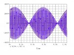
If the neutrals of the 2 inverters are tied together, and the "hots" never see a common load (no 240-volt loads), would there be a problem? The scenario is that the neutrals from the inverters would be landed on the neutral bar of the panel and the "hots" would be removed from the CB an wire-nutted to the "hots" from the inverters (separately of course). I have no idea what the L to L voltage would be from the 2 inverters, but don't really care since they are not going to be used in that manner.

My gut says they will be fine, but ... I'm not 100% positive but can't think of the scenario that there would be a problem. If there is one, I'm sure y'all will come up with it. :)
 

Hv&Lv

Senior Member
Location
-
Occupation
Engineer/Technician
I would think the LL waveform would be all over the place without synchronization. The two waves could be anywhere from 0-180 degrees based on Hz, giving all different kinds of LL voltages.
 

oldsparky52

Senior Member
I would think the LL waveform would be all over the place without synchronization. The two waves could be anywhere from 0-180 degrees based on Hz, giving all different kinds of LL voltages.

That is what I would expect also. Since there are no L to L loads, I did not consider it to be a problem.
 

LarryFine

Master Electrician Electric Contractor Richmond VA
Location
Henrico County, VA
Occupation
Electrical Contractor
As suggested above, as long as each output is isolated, one conductor from each of any number of sources can share a common conductor

They don't even have to have similar characteristics (voltage, frequency, etc.). The POCO system neutral is an example of this.
 

synchro

Senior Member
Location
Chicago, IL
Occupation
EE
If the hots share a neutral wire in a MWBC then during times when the inverters are in synch the currents will add together [2 x (1600W / 120V) = 26.7A max]. Depending on the duration they are in sync, the gauge the neutral wire and how fully loaded the inverters are, there could be an issue.
If there are separate neutral wires for the two branch circuits there's no problem
 

Besoeker3

Senior Member
Location
UK
Occupation
Retired Electrical Engineer
I would think the LL waveform would be all over the place without synchronization. The two waves could be anywhere from 0-180 degrees based on Hz, giving all different kinds of LL voltages.

Yes, but the OP says there will be no common 240V loads in which case synchronisation would not be an issue.
 

jaggedben

Senior Member
Location
Northern California
Occupation
Solar and Energy Storage Installer
If the waveforms are not synced then any common neutral conductor or busbar should be sized for the possibility of the neutral current being the sum of the hots.
 

Todd0x1

Senior Member
Location
CA
On some of these portable inverters the neutral is 60vac away from the chassis (ground, 0v, etc) and can't be connected to ground. Check that the inverters you're using can have the neutral connected to ground, otherwise you'll be in for a bad day.

From an inverter manufacturer: [h=3]10. What precaution should be taken in inverters where none of the current carrying conductors is bonded to the chassis?[/h] In some inverters designed for portable use, the two current carrying conductors connected to the "Line/Live/Hot" slot and the "Neutral / Return / Cold" slot of the receptacle ( for example, 15 A NEMA5-15R) are isolated from the metal chassis of the inverter. In these inverters, none of the two poles can be called Neutral as both these poles are isolated from the chassis of the inverter. Both the Line and Neutral slots of the receptacle will be at an elevated voltage with respect to the chassis - normally around 60 VAC (Half of the voltage between the two current carrying conductors). Hence, do not touch the neutral slot of the receptacle!

These types of inverters are designed to be connected directly to the AC loads. These are not designed to be permanently installed into household or recreational vehicle AC distribution wiring. As this type of connection / installation can not be classified as a permanent installation, the NEC requirement of grounded distribution system doesn't strictly apply.
 

synchro

Senior Member
Location
Chicago, IL
Occupation
EE
On some of these portable inverters the neutral is 60vac away from the chassis (ground, 0v, etc) and can't be connected to ground. Check that the inverters you're using can have the neutral connected to ground, otherwise you'll be in for a bad day.

From an inverter manufacturer: [h=3]10. What precaution should be taken in inverters where none of the current carrying conductors is bonded to the chassis?[/h] In some inverters designed for portable use, the two current carrying conductors connected to the "Line/Live/Hot" slot and the "Neutral / Return / Cold" slot of the receptacle ( for example, 15 A NEMA5-15R) are isolated from the metal chassis of the inverter. In these inverters, none of the two poles can be called Neutral as both these poles are isolated from the chassis of the inverter. Both the Line and Neutral slots of the receptacle will be at an elevated voltage with respect to the chassis - normally around 60 VAC (Half of the voltage between the two current carrying conductors). Hence, do not touch the neutral slot of the receptacle!

These types of inverters are designed to be connected directly to the AC loads. These are not designed to be permanently installed into household or recreational vehicle AC distribution wiring. As this type of connection / installation can not be classified as a permanent installation, the NEC requirement of grounded distribution system doesn't strictly apply.

I'm wondering if the chassis is at a voltage halfway between the neutral and hot line because there are filter capacitors from L and N to the chassis, and they both have the same capacitance value. If this was the case it wouldn't necessarily prevent bonding the chassis to neutral. But as Todd mentioned, it would be best to check with the manufacturer or supplier that such bonding is OK.
 

GoldDigger

Moderator
Staff member
Location
Placerville, CA, USA
Occupation
Retired PV System Designer
I'm wondering if the chassis is at a voltage halfway between the neutral and hot line because there are filter capacitors from L and N to the chassis, and they both have the same capacitance value. If this was the case it wouldn't necessarily prevent bonding the chassis to neutral. But as Todd mentioned, it would be best to check with the manufacturer or supplier that such bonding is OK.

Actually, the reason is that the (usually Modified Square Wave, MSW) output voltage waveform is created through a non-isolating autotransformer winding with its center tap grounded (connected to the battery or other DC source negative pole). That produces a balanced waveform on either side of that grounded center point. It is a cheaper construction method for the inverter output stage, even though it can cause serious problems with devices that expect the "neutral" to be the grounded conductor. It is not used when a 120/240 output is needed, just for single phase 120V AC.

If you ground the "neutral" you are directly shorting out the inverter AC output. Not a good thing!
 
Status
Not open for further replies.
Top