Question regarding NEC 705.12(D)(2)

Status
Not open for further replies.

rburnham

Member
Location
Gilbert, AZ USA
Hi,

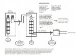
I am trying to get my 3-line electrical diagram approved by my local utility (SRP) in Arizona - I have already gotten approval from my AHJ. They have a problem with my proposed wire size going from my 200A aux breaker on my 400A main panel to my proposed 400A subpanel which will be connected to the 200A aux breaker located in the main panel. They asked me to send them a 3-line diagram with supporting NEC code that shows that the wire size proposed would be adequate. I attached what I sent to them here. This is their reply back to me:

According to NEC Section 705.12(D)(2) which states that ?the sum of breakers supplying power to a busbar or conductor shall not exceed 120% of the rating of the busbar or conductor?. The sum of the overcurrent devices (breakers) from both source of power adds up to be 325A (200A + 125A). According to this design, the governing component (busbar or conductor) between both overcurrent devices (breakers) would be the 2/0 CU rated for about 200A. Using the NEC requirement stated above, this design fails because 120% of 200A equals 240A .

My point to them is that the only way the wire feeding the subpanel can ever even see 200A is if there was a load on the subpanel that equaled 325A. That would allow 200A to come from the grid, and 125A come from the solar array. Also, the 2 inverters that will be backfeeding can only put out a max of 41.6A, but due to the 125% over-rating rule for breakers, I had to round up to 60A breakers, and then 125A combined breaker. So in reality, there can never be more than 84A being backfeed into the subpanel. Please let me know if this makes since and who is right on this one. Thanks.
 

Attachments

  • 3-line.JPG
    3-line.JPG
    143.6 KB · Views: 7

ggunn

PE (Electrical), NABCEP certified
Location
Austin, TX, USA
Occupation
Electrical Engineer - Photovoltaic Systems
To begin with, the breaker ratings that contribute to the 120% rule are the first breakers that the power from the inverters goes through, and that is a total of 120A. That number is carried all the way through the system to the interconnect. That includes the main panel as well; the ratings of any other breakers the power goes through are irrelevant to the calculation. The output current rating of the inverters is also irrelevant. The two 60A breakers (120A) is the only thing that counts from that direction.

As to your problem with the utility... unfortunately, since your subpanel has loads in it the conductors connecting the sub to the main are indeed being fed from both ends and are therefore subject to the 120% rule. By code they should be sized to handle (200A + 120A) * 0.833 = 266.66A minimum. It's the code; logic does not necessarily apply.

CAVEAT: The above are my opinions and could be proven wrong by someone who is more of a code expert than I.
 
Last edited:

Smart $

Esteemed Member
Location
Ohio
... Please let me know if this makes since and who is right on this one. Thanks.
Utility is correct.

The conductors between the main and sub, being MLO, must be rated at not less than (200 + 120) ? 120% = 267A

The other option is to use a 200 MCB for the 400A sub or backfeed it with a 200A breaker at the top.
 

rburnham

Member
Location
Gilbert, AZ USA
OK, so from what I'm hearing... logic doesn't always apply when dealing with NEC code. So my 2 options are to update the 3-line to show the wire feeding the subpanel to be 250 kcmil or I could put a 200A breaker on the 400A subpanel and backfeed through that. I think it would be better to just upgrade the wire size. Would it be acceptable to run (2) #1 AWG wires in parallel instead of the 250 kcmil wire? I think the 2 wire option would be less expensive and offer more ampacity.
 

Smart $

Esteemed Member
Location
Ohio
OK, so from what I'm hearing... logic doesn't always apply when dealing with NEC code. So my 2 options are to update the 3-line to show the wire feeding the subpanel to be 250 kcmil or I could put a 200A breaker on the 400A subpanel and backfeed through that. I think it would be better to just upgrade the wire size. Would it be acceptable to run (2) #1 AWG wires in parallel instead of the 250 kcmil wire? I think the 2 wire option would be less expensive and offer more ampacity.
Actually, 250kcmil @ 255A would be too small.

If you run parallel 1/0 copper, that would be okay as long as they are in two conduits. If you pull in the same conduit, derating applies and would take the ampacity below 267A.
 

texie

Senior Member
Location
Fort Collins, Colorado
Occupation
Electrician, Contractor, Inspector
Under the 2011 and prior NEC this is not compliant. In your case, given that the inverters are connected at the opposite end of the panel and hence the opposite end of the feeder, I agree that the feeder can't be overloaded.
That said, the 2014 705.12(D)(12)(2) has been revised. Note the new language that indicates that the conductor has to be sized for all sources when the inverters are NOT connected at the opposite end of the feeder supply. I think your situation was what they were trying to address with this revision.
I think it is nonsense to say you need to use a feeder conductor ampacity larger than the 200 amp breaker supplying it in your case. Now if there were loads tapped in this feeder ahead your 400 amp panel, this would be a different story and the new language address this.
 

rburnham

Member
Location
Gilbert, AZ USA
OK. I was looking at the 90?C temperature rating which shows 290A. If that doesn't work then it sounds like I would have to use 300 kcmil. I wouldn't want to run 2 separate conduit runs, so if I go the parallel route, then would 1/0 work in the same conduit? Thanks.
 

Smart $

Esteemed Member
Location
Ohio
OK. I was looking at the 90?C temperature rating which shows 290A. If that doesn't work then it sounds like I would have to use 300 kcmil. I wouldn't want to run 2 separate conduit runs, so if I go the parallel route, then would 1/0 work in the same conduit? Thanks.
I mispoke earlier...

Parallel 1/0 in same conduit may work using 90?C rated conductors. Derating for 4-6 conductors puts it at 272A. Correcting for ambient will be key. Also, if the run is underground, it'll have to be type rated for 90?C in wet conditions, such as THWN-2.
 

ggunn

PE (Electrical), NABCEP certified
Location
Austin, TX, USA
Occupation
Electrical Engineer - Photovoltaic Systems
OK, so from what I'm hearing... logic doesn't always apply when dealing with NEC code. So my 2 options are... ...or I could put a 200A breaker on the 400A subpanel and backfeed through that.
No. I mean, you could do that but it wouldn't fix anything. The contribution to the 120% rule in the conductors between the main and the sub is 120A (2 * 60A from the breakers connected to the inverters) no matter how it gets there. The contribution from the breaker in the main feeding those conductors is 200A.

What you could do, not that you'd want to, is reduce the size of the breaker in the main feeding the sub so that its rating plus 120A would be equal to or less than 120% of the 200A rating of the conductors. I figure that to be 120A. That's not a standard size; the next one down is 110A.
 
Last edited:

ggunn

PE (Electrical), NABCEP certified
Location
Austin, TX, USA
Occupation
Electrical Engineer - Photovoltaic Systems
I read the code rule as requiring the use of the rating of the overcurrent device that is in the panel.
No, the code says that the rating(s) of the first breaker(s) connected to the inverter(s) is/are carried in 120% rule calculations all the way to the interconnect.
 

rburnham

Member
Location
Gilbert, AZ USA
I want to thank everyone for their quick responses. I am going to resubmit my 3-line showing 250 mil THHN which is 90 deg. rated which will handle 290A. Hopefully this will fly. If not, I can always resubmit using 300mil. Thanks again, Russell
 

ggunn

PE (Electrical), NABCEP certified
Location
Austin, TX, USA
Occupation
Electrical Engineer - Photovoltaic Systems
I want to thank everyone for their quick responses. I am going to resubmit my 3-line showing 250 mil THHN which is 90 deg. rated which will handle 290A. Hopefully this will fly. If not, I can always resubmit using 300mil. Thanks again, Russell
Are your terminals rated at 90 degrees C?
 

BillK-AZ

Senior Member
Location
Mesa Arizona
Check for 75?C terminal ratings

Check for 75?C terminal ratings

You also have to consider the temperature ratings of the terminals on both ends of the cable. Most load centers are Listed for 75?C conductors.

Most of the SRP service area can have ambient temperatures of 113?F or higher. If you have 75? terminals and 105-113?F ambient per table 310.15(B)(2) the correction factor is .82. 267A/.82 = 325.6A. Looks like 400mcm CU.

If your 400A main panel is Sun Valley Electric, you can likely get a line side connection kit and use 200A fused AC Disconnects. Not sure about SRP, but APS requires two AC disconnects for line side connection, the one connecting to the service needs to be fused and has owner access, the other is for the utility to disconnect for service.
 

Smart $

Esteemed Member
Location
Ohio
You also have to consider the temperature ratings of the terminals on both ends of the cable. Most load centers are Listed for 75?C conductors.

Most of the SRP service area can have ambient temperatures of 113?F or higher. If you have 75? terminals and 105-113?F ambient per table 310.15(B)(2) the correction factor is .82. 267A/.82 = 325.6A. Looks like 400mcm CU.

...
Ambient correction does not apply to conductor sizing for terminal temperature limitations. 300kcmil copper with a 285A@75?C allowable ampacity is sufficient for this determination. Don't forget this determination already has an extra 25% for continuous loads built-in to the 267A value.

However, ambient correction does apply to conductor sizing for ampacity... and can be done with 90?C values if using 90?C rated conductors. Correction factor for 105-113?F is 0.87@90?C.
267A ? 0.87 = 307A. 300kcmil copper with a 320A@90?C allowable ampacity before correction is sufficient for this determination.
 
Last edited:

texie

Senior Member
Location
Fort Collins, Colorado
Occupation
Electrician, Contractor, Inspector
Under the 2011 and prior NEC this is not compliant. In your case, given that the inverters are connected at the opposite end of the panel and hence the opposite end of the feeder, I agree that the feeder can't be overloaded.
That said, the 2014 705.12(D)(12)(2) has been revised. Note the new language that indicates that the conductor has to be sized for all sources when the inverters are NOT connected at the opposite end of the feeder supply. I think your situation was what they were trying to address with this revision.
I think it is nonsense to say you need to use a feeder conductor ampacity larger than the 200 amp breaker supplying it in your case. Now if there were loads tapped in this feeder ahead your 400 amp panel, this would be a different story and the new language address this.
I'm quoting my own post as all seem to have ignored it. There is no engineering reason for you to size the feeder conductors as you are being asked to do by the POCO. Yes, as I said in my post #8, I recognize the 2011 NEC would require it to be so but this has been addressed in the 2014. You said the AHJ approved this as drawn (maybe they see the obvious) but the POCO says no. If this a long run that will cost money, why don't have a discussion with the POCO and show them that the NEC now recognizes the obvious.
 
Status
Not open for further replies.
Top