Reactance Questions on Conductors

wwhitney

Senior Member
Location
Berkeley, CA
Occupation
Retired
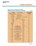
NEC Chapter 9 Table gives reactances for "3-Phase, 60 Hz . . . Three Single Conductors in Conduit." The notes say "capacitive reactance is ignored," so this is an inductive reactance. A few questions:

1) For PVC conduit, I take it this is the impedance attributable to the current in one of the 3 conductors inducing an opposing current in the other two conductors (in aggregate, for all pairs of conductors). How would these values change for a single phase 2-wire circuit, or the case of a 3P4W wye supply, or a 3P3W supply plus a wire type EGC, or 6 conductors for 2 parallel sets on a 3P3W supply?

2) For steel conduit we get a higher reactance than PVC. If we have a wire type EGC as a 4th conductor in the conduit, how will the 60 Hz reactance change if that steel conduit is bonded to the wire type EGC at 0 ends, 1 end, or 2 ends? [0 ends, of course, is usually an NEC violation.]

Thanks,
Wayne
 

David Castor

Senior Member
Location
Washington, USA
Occupation
Electrical Engineer
Inductive reactance in conductors can be divided into two components: the self-reactance of the conductor itself and the mutual reactance between adjacent conductors. The mutual inductance depends on the configuration and spacing of the conductors in the conduit. Even a single conductor in free air has inductance. I don't believe that bonding of the conduit will have much impact on reactance of conductors inside the conduit, but I haven't thought about that in a long time.
 

Elect117

Senior Member
Location
California
Occupation
Engineer E.E. P.E.
Isn't it lenz's law? Or maybe Faraday's? Or Eddy currents. I can't remember which one is the explanation. They all probably relate.

The field gets directionally apposed by conductive conduits that results in a higher impedance of an AC circuit. It wouldn't be a rise in resistance since that is independent of rate of change. As the field changes from + to - and - to + the induced field and current appose electron flow.

1) The fields shouldn't be effected by PVC but instead they would be effected by each other (which you say) and their configurations. The same reason why you have to run all the circuit conductors in the same conduit. The distance can induce a voltage gradient and then the fields won't cancel.

2) I don't think bonding the steel conduit to a better 0V point would help. The field would still follow as current changes polarity in the conductor. The only question would be based on the position of the EGC if it's field would cancel the field on the conduit which could remove induced voltage? Like bonding both ends of a cable sheath in HV underground lines.
 

Julius Right

Senior Member
Occupation
Electrical Engineer Power Station Physical Design Retired
The reactance in MKSA [IEC-SI] units' system it is:
Xc=2*pi()*f*(K+0.2*ln(2*s/dc))/10^3
Where:
f=system frequency [Hz]
S=the equivalent distance[m]
dc=conductor diameter[m]
Xc=the reactance[ohm/km]
K=a factor depending on number of strands in a conductor.
If 4*pi()*f*ln(2*S/dc)/10^4 it is the mutual part then 2*pi()*f*K/10^3 it is the self-inductance of one conductor part.
The calculation following the Neumann formula, derived from the magnetic vector potential and Faraday's law of induction, gives an analytical solution of the mutual inductance.
For instance, Okonite Engineering Handbook presents an abacus for reactance calculations in Imperial units.However, the self-inductance part it is only for solid [non-stranded] conductor.
X=2*pi*f*(0.1404*log10(2*S/r)+0.0153)/10^3 [ ohm/1000ft]
S=the equivalent distance [for two parallel straight conductors S it is the actual distance].


No. of wire strands in conductor
K
3​
0.0778​
7​
0.0642​
19​
0.0554​
37​
0.0528​
>60
0.0514​
1 (solid)
0.05​
 
Last edited:

wwhitney

Senior Member
Location
Berkeley, CA
Occupation
Retired
The reactance in MKSA [IEC-SI] units' system it is:
Thank you for the formula!

S=the equivalent distance [for two parallel straight conductors S it is the actual distance].
So I think you've told me enough to be able to use the formula you gave for the case of 1 conductor (just use the self-inductance term) and for 2 conductors. But how do you determine the "equivalent distance" when there are 3 or more conductors? Or can you just consider all pairs consisting of the conductor in question and one of the other conductors, and add the mutual inductance terms for each such pair to the self-inductance term?

Cheers, Wayne
 

Julius Right

Senior Member
Occupation
Electrical Engineer Power Station Physical Design Retired
See Okonite Reactance Abacus
 

Attachments

  • Okonite Reactance.jpg
    Okonite Reactance.jpg
    61.1 KB · Views: 6

Julius Right

Senior Member
Occupation
Electrical Engineer Power Station Physical Design Retired
Based on formula
 

Attachments

  • Based on formula.jpg
    Based on formula.jpg
    69.5 KB · Views: 5

wwhitney

Senior Member
Location
Berkeley, CA
Occupation
Retired
Based on formula
Thanks, that covers the case of 3 conductors. Since that formula for s is the geometric average of the pairwise distances, is that how it generalizes to four or more? E.g. with 4 conductors, there are six pairwise distances, so s would be the sixth root of the product of those distances?

I'm a little surprised it doesn't explicitly scale linearly with the number of conductors, but maybe given that the conductors are non-overlapping, it effectively does just from the behavior of s.

Does this formula still hold when the distance between conductors is large, like 20'?

Cheers, Wayne
 

MyCleveland

Senior Member
Location
Cleveland, Ohio
Thanks, that covers the case of 3 conductors. Since that formula for s is the geometric average of the pairwise distances, is that how it generalizes to four or more? E.g. with 4 conductors, there are six pairwise distances, so s would be the sixth root of the product of those distances?

I'm a little surprised it doesn't explicitly scale linearly with the number of conductors, but maybe given that the conductors are non-overlapping, it effectively does just from the behavior of s.

Does this formula still hold when the distance between conductors is large, like 20'?

Cheers, Wayne
To your last sentence…look up posts by “Mivey”…hope I recalled the name correctly. He provided detailed help on this topic that I was able to code it into excel and later into an app.
 

Julius Right

Senior Member
Occupation
Electrical Engineer Power Station Physical Design Retired
Since the intention is to state the maximum voltage drop, the equivalent reactance is considered for symmetrical currents. So, we have only 3 loaded conductors [no neutral loaded].
For 2 parallel three-phase single-core cables we can use the theory of transmission line wires defining GMD and GMR.
The equivalent inductance is L=μo*ln(GMD/GMR). μo=2/10^7 H/m
From conductor manufacturer catalogue we get a GMRc for a stranded conductor.
For solid [not stranded] conductor req=r*e^(-1/4)=0.7788*r where r conductor radius.
If the conductors of phase A ,B and C of the first group are a1,b1 and c1, for the second parallel group will be a2,b2 and c2.
Let’s define GMR=(DSA*DSB*DSC)^(1/3) where:
DSA=SQRT(GMRc*Da1a2)
DSB=SQRT(GMRc*Db1b2)
DSC=SQRT(GMRc*Dc1c2)
And define GMD=(DAB*DBC*DCA)^(1/3) where:
DAB=(Da1b1*Da2b1*Da1b2*Da2b2)^(1/4)
DAC=(Da1c1*Da2c1*Da1c2*Da2c2)^(1/4)
DBC=(Db1c1*Db2c1*Db1c2*Db2c2)^(1/4)
Then Xc=2*pi()*f*L
For voltage drop you have to combine with the resistance [Z=R/2+jXc] and amplify by sqrt(3)≈1.73 for three phases or by 2 for phase-to-phase system.
 
Last edited:
Top