real world measuement: electronc ballasts on MWBC's

Status
Not open for further replies.
I installed a bunch of 1000W HPS electronic ballasts on full boat 277 MWBC's. Each fixture have line current of 3.9 amps, 4 fixtures per circuit, so 12 fixtures per boat. The neutral current was about 2.7 amps. Just seems kinda insignificant to me which is on contrast to all the doom and gloom about non linear loads, super neutrals, 4 CCC...... Does anyone have any figures from measurements with electronic ballasts?
 

steve66

Senior Member
Location
Illinois
Occupation
Engineer
I installed a bunch of 1000W HPS electronic ballasts on full boat 277 MWBC's. Each fixture have line current of 3.9 amps, 4 fixtures per circuit, so 12 fixtures per boat. The neutral current was about 2.7 amps. Just seems kinda insignificant to me which is on contrast to all the doom and gloom about non linear loads, super neutrals, 4 CCC...... Does anyone have any figures from measurements with electronic ballasts?

No measurements, but the worst typical electronic ballast would have 20% THD. At worst case, that could mean 60% of the rated current on a neutral conductor. That wouldn't require an oversized neutral. Most engineers specify 10% THD, so that would only be 30% of rated current on the neutral.

I suspect that LED drivers are much better, and have a much lower THD. So that would mean even less current on the neutral.

Good info thanks. How are you converting THD to neutral current?
 

dionysius

Senior Member
Location
WA
I installed a bunch of 1000W HPS electronic ballasts on full boat 277 MWBC's. Each fixture have line current of 3.9 amps, 4 fixtures per circuit, so 12 fixtures per boat. The neutral current was about 2.7 amps. Just seems kinda insignificant to me which is on contrast to all the doom and gloom about non linear loads, super neutrals, 4 CCC...... Does anyone have any figures from measurements with electronic ballasts?

Interesting info. Thanks. What do you mean by "full boat" ??
 

steve66

Senior Member
Location
Illinois
Occupation
Engineer
Good info thanks. How are you converting THD to neutral current?

It's more like a worst case estimate than an actual conversion.

The definition of THD is: 100% x Harmonic Current / Total current.

So on a 20 amp circuit where the THD is 20%, we would have 4 amps of THD current.

Worst case is that all those currents add together on the neutral, so a full boat could have 3x4 amps = 12 amps on the neutral. It will cause some added voltage drop on the circuit, but it definitely won't overheat a #12 neutral wire.
 

JFletcher

Senior Member
Location
Williamsburg, VA
I installed a bunch of 1000W HPS electronic ballasts on full boat 277 MWBC's. Each fixture have line current of 3.9 amps, 4 fixtures per circuit, so 12 fixtures per boat. The neutral current was about 2.7 amps. Just seems kinda insignificant to me which is on contrast to all the doom and gloom about non linear loads, super neutrals, 4 CCC...... Does anyone have any figures from measurements with electronic ballasts?

All these fixtures are L-N? If so, what would be the neutral current if you lost a phase and didnt have the natural cancellation of 3 120* currents?
 

dionysius

Senior Member
Location
WA
A request if you have time......OP

A request if you have time......OP

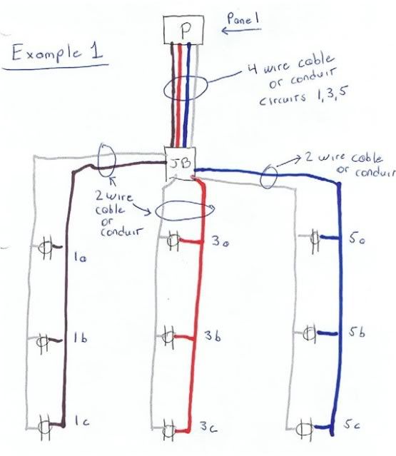
It would help us all to follow this very important discussion if you had a sketch or schematic of the cct since I see some different views being assumed here. Are loads in parallel or in series??? If you can find the time you might do a pencil sketch and attach a picture of it so we are clearly all on the same page.
 

iwire

Moderator
Staff member
Location
Massachusetts
Are loads in parallel or in series???

Loads are in parallel as they always are.

The source is 480Y/277. He has a number of fixtures connected to phase A, a number of fixtures connected to phase B, a number of fixtures connected to phase C. All these fixtures are connected to a single neutral. This makes it a multiwire branch circuit.

Branch Circuit, Multiwire. A branch circuit that consists
of two or more ungrounded conductors that have a voltage
between them, and a grounded conductor that has equal
voltage between it and each ungrounded conductor of the
circuit and that is connected to the neutral or grounded
conductor of the system.
 

iwire

Moderator
Staff member
Location
Massachusetts
Replace the receptacle outlets with light fixtures and you have a rough diagram of what the OP has.

MWBC1001.jpg
 

dionysius

Senior Member
Location
WA
Thank you IWire for this info and schematic.

1. Am I correct in saying that if everything were perfectly balanced (ph1 = ph2 = ph3) then the neutral would be theoretically zero amps?????


2. Q re MWBC definition here:
Branch Circuit, Multiwire. A branch circuit that consists
of two or more ungrounded conductors that have a voltage
between them, and a grounded conductor that has equal
voltage between it and each ungrounded conductor of the
circuit and that is connected to the neutral or grounded
conductor of the system.​

There is nothing grounded in the schematic so is the MWBC definition satisfied or is it implied that N is conn to Grd since P is a MBP????

3. Is the message here that the neutral can be same gauge as the phases or can it be smaller and if so by how much to meet code????
 

junkhound

Senior Member
Location
Renton, WA
Occupation
EE, power electronics specialty
Does anyone have any figures from measurements with electronic ballasts?

Varies greatly between ballast mfg, from the 20% mentioned down to nil (with 0.99+ PF)

If the electronic ballast has a PFC (power factor correction) boost circuit, below 1% harmonics.

Plot of a ballast for aircraft, 2 different chips used for PFC circuit as noted. This is on a 400 Hz power line, PFC on 60 Hz circuit has under 1/2 the harmonic level for similar type boost PFC circuitry.
Pf.jpg
 
How did you measure nuetral current? If your meter/clamp is not true rms it will have trouble reading harmonics.

Yes, using a higher end fluke meter, should be accurate. Although can the sampling rate of the meter, even if true RMS, be too low to "Catch" all the harmonics?

All these fixtures are L-N? If so, what would be the neutral current if you lost a phase and didnt have the natural cancellation of 3 120* currents?

Yes all L-N. Thats a good question. Since in a 3 wire, 3 phase MWBC the neutral carries about the same current as the phase conductors, would this circuit be more likely to have an overloaded neutral due to harmonics?

Thank you IWire for this info and schematic.

1. Am I correct in saying that if everything were perfectly balanced (ph1 = ph2 = ph3) then the neutral would be theoretically zero amps?????


2. Q re MWBC definition here:
Branch Circuit, Multiwire. A branch circuit that consists
of two or more ungrounded conductors that have a voltage
between them, and a grounded conductor that has equal
voltage between it and each ungrounded conductor of the
circuit and that is connected to the neutral or grounded
conductor of the system.

There is nothing grounded in the schematic so is the MWBC definition satisfied or is it implied that N is conn to Grd since P is a MBP????

3. Is the message here that the neutral can be same gauge as the phases or can it be smaller and if so by how much to meet code????

1. Yes, but electronic loads can make this not the case.
2. I dont quite get the question, but whether the system is grounded or not has no bearing on the neutral current.
3. The neutral of a feeder is technically sized by a load calculation. In practice, three phase feeders usually have full size neutrals, and single phase neutrals are often two sizes smaller. I am not sure if we are ever allowed to reduce the neutral on a branch circuit, but I dont think so.

Varies greatly between ballast mfg, from the 20% mentioned down to nil (with 0.99+ PF)

If the electronic ballast has a PFC (power factor correction) boost circuit, below 1% harmonics.

Plot of a ballast for aircraft, 2 different chips used for PFC circuit as noted. This is on a 400 Hz power line, PFC on 60 Hz circuit has under 1/2 the harmonic level for similar type boost PFC circuitry.

Cool info thanks!

IMO the NEC and industry needs to catch up a little on this topic. The NEC is just black and white, linear or not, which seems a bit out of date. For example in my case, should I have to count the neutral as a CCC?
 

JFletcher

Senior Member
Location
Williamsburg, VA
Yes all L-N. Thats a good question. Since in a 3 wire, 3 phase MWBC the neutral carries about the same current as the phase conductors, would this circuit be more likely to have an overloaded neutral due to harmonics?

Was just thinking that a oversized neutral would be needed more if you lost a phase and the ballasts had a high THD. In a perfectly balanced 3ph 4 wire circuit with pure resistive loads, AN = 0. The distortions dont cancel out perfectly tho, which I dont quite get... I'll have to study up on that.

With your application, I dont think even a phase loss wouldnt push the neutral over 20A... being limited to 80% of the breaker for a continuous load gives some leeway for THD.

If you were to lose the neutral of the MWBC, then what happens to that 2.7A? Would it return on the other phases, raising them the 18.3A (15.6+2.7) or higher? Assume for a moment that all 3 legs see an identical load.
 

iwire

Moderator
Staff member
Location
Massachusetts
Was just thinking that a oversized neutral would be needed more if you lost a phase and the ballasts had a high THD.

But really would you need a oversized neutral?

What is the true rating of a 12 AWG copper vs what we protect it at?

12 AWG CU is rated 25 amps @ 75C
 

mbrooke

Batteries Included
Location
United States
Occupation
Technician
But really would you need a oversized neutral?

What is the true rating of a 12 AWG copper vs what we protect it at?

12 AWG CU is rated 25 amps @ 75C

Assuming all terminals are rated for 75*C. Which is probably the case since the neutral is just one long splice string but still something to think about.
 

MD84

Senior Member
Location
Stow, Ohio, USA
Yes, using a higher end fluke meter, should be accurate. Although can the sampling rate of the meter, even if true RMS, be too low to "Catch" all the harmonics?

In the case of a steady state operation such as this a true rms measurement should capture all current.

Sample rate comes in to play for other than steady state operation such as starting or inrush current.
 
Status
Not open for further replies.
Top