Which also means that when upsizing a 120V circuit for VD, it could be cheaper to upsize the grounded conductor more than the ungrounded conductors.
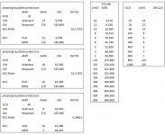
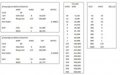
For example, on a 20A circuit, #12 solid copper has a DC resistance of 1.93 ohms/kft (per Chapter 9 Table 8, although maybe I should be using Table 9 instead). Say for VD reasons you need to get that down to 0.9 ohms/kft. You could use #8 stranded conductors (0.778 ohms/kft), and you'd need (3) #8s (ungrounded, grounded, EGC).
Or you could use a #6 grounded conductor (0.491 ohms/kft) and a #10 stranded ungrounded conductor (1.24 ohms/kft), for an average of 0.866 ohms/kft. That would let you use a #10 EGC. So if (2) #10s + (1) #6 is cheaper/easier than (3) #8s, that's an option (with a bit more VD, as 0.866 > 0.778).
Cheers, Wayne