mstrlucky74
Senior Member
- Location
- NJ
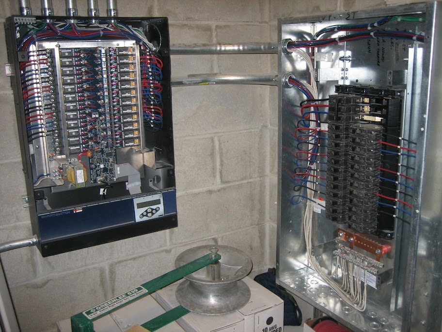
Need a little help(see attached). Ok so with a lighting control panel the line voltage ckts come from the lighting panel into the relay panel. This is where I'm not clear. Do you have low voltage wiring thst goes form the relay panel out to the lights? I've seen drawing where it says" Lighting control panel Zone 3-1(corridor) so I'm assuming LV wiring is ran out to the lights but where would the LV terminated if the lights are line voltage? A power pack? Thanks