REQUEST: Load (in Watt) and CB size calculations

Status
Not open for further replies.

smileyrules

Member
Location
toronto
Gents,

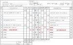
I am connecting two devices to a panel (DP. VOTLS: 208/102, MAIN AMPS: 225) with columns A B C. values are entered in WATTS.

First Device: 208VAC, 3Phase, 30A, 60Hz.
Second Device: 120VAC, 1Phase, 30A, 60Hz.

How much wattage in each columns: ABC?
What CB size should be used for each device?

Kindly, provide the proper calculations because I lost my mind going over this with a pencil and paper.


Thank you.
 
The question cannot be answered without additional information. Let's start with this:
  • If you are talking about entering information into the columns of a panel schedule, then you need to enter VA, not watts.
  • If the panel schedule you are using shows watts in the load columns, then it is wrong.
  • For single phase loads, the value of VA is found by simply multiplying the voltage (120 for your second device) times the current. You show the current for the second device as 30, but I am not convinced that that is right. Where did that number come from?
  • For three phase loads, the value of VA is found by multiplying the voltage (208 for your first device) times the current, then multiply by 1.732 (i.e., the square root of 3). Here again, you show the current for the second device as 30, but I am not convinced that that is right. Where did that number come from?
  • In order to size the circuit breaker, you need to know what kind of load it will serve. Also, you need to know whether it is a "continuous load." That phrase is defined as a load that will operate at full capacity for a period of three hours or longer.

If you could fill in some of the blanks, we might be able to help you through this process.
 
Hello and thank you for your assistance.

please find the attached photos illustrating the current situation.
  1. DP CONNECTION
  2. DEVICE 1 - A
  3. DEVICE 1 - B
  4. DEVICE 2

Note 1: I learned that the second device will draw approximately 23.5Amp, yielding 2.82kW. the remaining is the CB rating?
Note 2: we are always considering the load as continuous.
 

Attachments

  • DP CONNECTIONS.jpg
    DP CONNECTIONS.jpg
    29 KB · Views: 1
  • DEVICE 1 - A.jpg
    DEVICE 1 - A.jpg
    16.5 KB · Views: 1
  • DEVICE 1 - B.jpg
    DEVICE 1 - B.jpg
    18 KB · Views: 0
  • Device 2.jpg
    Device 2.jpg
    10.2 KB · Views: 0
Let's start with device #2. At 120 volts, the value of 2.82 KW does correlate with 23.5 amps. To size a circuit breaker for a continuous load, you need to add 25% to the 23.5 amps, and that gives you 29.4 amps. So the 30 amps they gave you is the right size for the circuit breaker. On the panel schedule, you show the load as 2820 VA. As I mentioned earlier, the panel schedule incorrectly shows watts. That is going to come into play with device #1, but does not impact device #2.

Regarding device #1, I cannot read the text of your attachments. The images are not clear enough. I see that there are motors involved. But I can't tell the horsepower ratings. Also, it is not clear to me how many loads (motors and other items) that the one circuit breaker will be supplying. So I can't take the next step.

I will say that for motors, "watts" and "VA" are not the same. The difference is the "power factor," and you probably don't have a value for that. This is one of the reasons that the panel schedule needs to be showing load values in terms of VA, and not in terms of watts.

If we can take the value of 30 amps for device #1 as being the breaker size that the manufacturer is calling for (which appears to be the case for device #2), then I would use the calculation that I showed earlier. 30 amps times 208 volts times 1.732 gives you 10,808 watts. You assign one third of this value to each column (i.e., 3,603 VA in each of columns A, B, and C). You then show the 30 amp breaker that the manufactuer has called for.
 
thank you, actually the first two pumps plus the agitator are typical with 0.75HP (560W each),
then there are two additional pumps (25W each),
a control panel (540W),
and another load connected through the JB (1055W)

My thinking was to add all the wattage connected on each phase since the existing drawing display results in watts:

L1: (560* 1.732)+1055 = 2025W ----A
L2: (560* 1.732)+540 = 1510W ----B
L3: (560* 1.732)+25+25 = 1020W ----C

does this make sense?
 
Status
Not open for further replies.
Top