Sounds like the ol' RLC Combination circuit stuff that I remember so fondly.
An inductor in an AC circuit will create inductive reactance in the circuit (why, exactly, I still only somewhat grasp). But the bottom line is that it unsynchronizes the current and voltage waveforms from each other. Similar but opposite effect with capacitors. So depending on how you arrange a circuit (series vs. parallel) containing inductors and resistors, the total circuit impedance will vary accordingly.
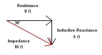
The inductive reactance can be represented by a vector, with a magnitude and a direction (in this case, the magnitude is however many ohms of inductive reactance are in the circuit, in a direction 90 degrees deflected from the resistive component). The circuit resistance does not contribute to any leading or lagging current, so its vector is simply the magnitude of resistive ohms in a direction of 0 degrees. If there were any capacitors in the circuit creating capacative reactance, they would have a vector also, 90? from the resistive vector and 180? from the inductive reactance vector. So in a circuit containing both capacitors and inductors, their respective current-opposing attributes will cancel each other out to the extent of their magnitude. Example: circuit with 5 ohms of inductive reactance and 2 ohms of capacative reactance. These reactances oppose each other vectorially opposite, so they would cancel out, leaving only 3 ohms of inductive reactance - closer to zero than before (why we use capacitors to correct power factor on big motor circuits and stuff).
Here's my primitive artistic skills in action:
The total amount of capacitive or inductive reactance in a circuit is determined by how it is wired. Inductors in series or parallel are calculated similarly to resistors. Capacitors are opposite. Once the numbers are boiled down to a single value then the vector math applies and you can figure out what the total circuit impedance is.


