120103-2145 EST
Something does not compute.
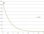
The time constant of 40 ohms and 16.8 ufd is 672 microseconds. At 3.4 milliseconds, 5 time constants, the current will drop to 0.006 of its initial value.
For reference i(t) = Iinitial * e^(-t/RC).
Was the initial current measured at at 22 A or just calculated?
Let us assume the initial current was 22 A and it dropped to essentially 0 in 3.4 milliseconds, then without calculating the energy I will guesstimate using 1 time constant that the energy is 22*850*0.00067*0.7 = 8.8 watt-seconds. Peanuts for a 100 W Ohmite resistor once per half hour. A 100 W resistor is about 10 inches long and 850 V would be no problem. Also there is no problem putting 400 V on a 1/2 W resistor about 1/2 inch long.
If the current does take upwards of 1 second to reach near 0 current, then the initial current is much less than 22 A, and something other than the 40 ohm resistor is limiting the current.
A different way to view the energy into the resistor is to calculate the total energy transferred to the capacitor. This is E = C*V^2/2 = 16.8*10^(-6)*0.85^2*10^6/2 = 6 watt-second. Assume an equal amount is dissipated in the resistor as is put into the capacitor, then 6 watt-seconds went into the resistor.
I bet the resistor is cool to the touch to just charge the capacitor. If there is a continuous load current on the supply containing the the capacitor after the capacitor is charged, then the resistor can get quite hot. At 4 A this would be 4*4*40 = 640 W.
I would have no problem putting 6 watt-seconds into a 1 W resistor every half hour.
Check my math and see if it is correct.
.
") no thanks. I am already using 600w resistor and seems to be working fine. I think you are being way too conservative. I have about 22A through the resistor at t=0 and current goes to zero in a couple of seconds...
no thanks. I am already using 600w resistor and seems to be working fine. I think you are being way too conservative. I have about 22A through the resistor at t=0 and current goes to zero in a couple of seconds...