I was asked to check out a wiring problem in a recently purchased home. I was told the homeowner had just installed an internet connection by the local cable company. he plugged in a surge protector for both the electric and the internet connection. when plugging in the cable for the internet connection he blew the mother board, twice. Cable co. and local power co. checked and said all was ok at their end. the homeowner told me when buying the house, he asked for one receptacle in each room be grounded. Being a rehabbed home, it raised my suspicion of something I have seen before. Someone had installed a jumper between the neutral and ground screw so a plugin type tester would show correct wiring. Here's the thing. it also had reverse polarity. I first checked it with my plug in tester, it showed ok. shouldn't this have shown the reverse polarity on the tester? This is a very dangerous situation, and almost missed it myself, because my plug in tester showed that it was wired correctly. has anyone else run across this ?????
You are using an out of date browser. It may not display this or other websites correctly.
You should upgrade or use an alternative browser.
You should upgrade or use an alternative browser.
reverse polarity
- Thread starter frank112
- Start date

- Status
- Not open for further replies.
eric stromberg
Senior Member
- Location
- Texas
You need a new plug tester. It should have immediately pickep up the 120 between N-G.
Dereck,
From what i read in the post, it didn't appear to me that there was 120 Volts between the Ground and the Neutral.
It appears as though the Neutral and Ground are jumpered together, as well as being wired in reverse polarity. This would put the 'hot' blade at 0 Volts and the Neutral/Ground at 120 Volts.
I agree he needs a new tester, but i think i'll replicate this one at the house and see what my tester shows.
Eric
Re: reverse polarity
Yes it should have.
You should contact the tester manufac. and let them know of the condition/hazard you discovered AND the fact that their tester DID NOT PERFORM PROPERLY....makes one wonder about their other products.
So, what brand/model tester was it?
I have an assortment of them - maybe I can duplicate the scenario.
frank112 said:shouldn't this have shown the reverse polarity on the tester?
Yes it should have.
You should contact the tester manufac. and let them know of the condition/hazard you discovered AND the fact that their tester DID NOT PERFORM PROPERLY....makes one wonder about their other products.
So, what brand/model tester was it?
I have an assortment of them - maybe I can duplicate the scenario.
curt swartz
Electrical Contractor - San Jose, CA
- Location
- San Jose, CA
- Occupation
- Electrical Contractor
The tester doesn?t know the difference between a grounded conductor (neutral) and non-grounded conductor (hot). It is simply looking for voltage between each of the 3 conductors (ground, neutral and hot). It should show voltage from hot to neutral and hot to ground but not ground to neutral. If the hot wire is connected to the neutral and ground terminals and the neutral wire is connected to the hot terminal the tester will show the receptacle as wired correctly.
curt swartz said:The tester doesn?t know the difference between a grounded conductor (neutral) and non-grounded conductor (hot). It is simply looking for voltage between each of the 3 conductors (ground, neutral and hot). It should show voltage from hot to neutral and hot to ground but not ground to neutral. If the hot wire is connected to the neutral and ground terminals and the neutral wire is connected to the hot terminal the tester will show the receptacle as wired correctly.
If that is the case, then HOW does a tester show:
- Correct wiring
- Open Ground
- Rev. Polarity
- Hot & Ground reversed
- Hot on neutral w/ground open
If the tester is ONLY looking for H-N-G, how is even possible to show a reverse situation ???
I used an Ideal GFCI tester. I haven't had the chance to retest on a receptacle that I know is right, but in other receptacles in the house that had the jumper but not reverse polarity, I had the same results on the tester. A little scary and a heads up to all about a dangerous situation.
ramsy
NoFixNoPay Electric
- Location
- LA basin, CA
- Occupation
- Service Electrician 2020 NEC
Ideal GFCI testers, also known as "ShureTest" are supposed to detect this.
"E_rP" for reverse polarity.
"E_FG" for false ground, except within 15 ft of panel / main bondings.
"E_rP" for reverse polarity.
"E_FG" for false ground, except within 15 ft of panel / main bondings.
Curt most of the testers out there put some kind of load on the UUT between L-N and L-G than take readings between all conductors. From thos voltages the device can correctly identify all conductors, voltage drop percentage, bootleg grounds, reversals, etc.curt swartz said:The tester doesn?t know the difference between a grounded conductor (neutral) and non-grounded conductor (hot).
curt swartz
Electrical Contractor - San Jose, CA
- Location
- San Jose, CA
- Occupation
- Electrical Contractor
Hello Dereck
Maybe I?m misunderstanding this post. I was under the impression that the hot wire of the circuit was connected to the neutral terminal of the receptacle and the neutral wire was connected to the hot terminal. A jumper was then placed between the neutral terminal and the grounding terminal.
If that?s the case no matter what type of tester is used it still does not know which conductors are grounded and which are hot. You would need a 4th reference wire to make that determination. Even if the tester used puts a load on the circuit the receptacle will not show reversed polarity. I have never used the type of tester used for this test but accept that it should show a problem with this receptacle because of the jumper between the neutral terminal and grounding terminal. It still doesn?t know the hot and neutral connections are reversed. There will be voltage between the hot terminal and the neutral terminal, between the hot terminal and the grounding terminal and no voltage between the neutral terminal and grounding terminals.
- Location
- Windsor, CO NEC: 2017
- Occupation
- Hospital Master Electrician
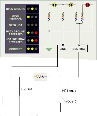
This is a schematic of a plug tester, which has had the lower portion doctored to show how a "Hot/Ground Reversed" can be indicated when the real problem is an open neutral.
Looking at the schematic, it seems to me that if the ground and neutral pins were energized, and the line pin was the neutral, then it would read as a grounded, correctly polarized receptacle.
I thought some brands of testers used diodes to give more accurate indications?
allenwayne
Senior Member
If you rely on just a plug tester to troubleshoot then you will be chasing your own tail for days on end.I use a plug tester to determine that a circuit is working properly if a fault is found then it gets put away and my fluke comes out. :wink: First I check for hot to ground and then neutral then I will check for voltage reading from neutral to ground,then continuity from neutral to ground.That way I know if all parts are working properly.You have to watch digital meters as they will show ghost voltage from a switching system but as you learn your meter you will be able to know what is real and what is a ghost.But I ain`t afraid of no ghosts 
LarryFine
Master Electrician Electric Contractor Richmond VA
- Location
- Henrico County, VA
- Occupation
- Electrical Contractor
The best troubleshooting tool I know is a 3-wire extension cord plugged into a known-good grounded receptacle, which provides a portable reference for hot, neutral, and ground, along with a solenoid-type tester. This is especially good on a circuit with no grounding, such as K & T, and using it would have caught this mis-wire.
allenwayne
Senior Member
Each type of tester has its own faults either a digital or solenoid type.For years I swore on a solenoid (wiggy) but once I learened my digital fluke`s oddities I found that from the ghost reading you can tell from the start things like if a 3 way 1/2 switched receptacle was cut in wrong from the ghost voltage at the receptacle.That would have taken a bit of time with a solenoid tester.But a solenoid tester shows a dead short quicker than my digital does.I guess it is at that point a matter or preference.To me give me my fluke and hands down I find the problem and solution quicker than I did with a solenoid tester. 8)
busman
Senior Member
- Location
- Northern Virginia
- Occupation
- Master Electrician / Electrical Engineer
In working through the normal DMM tests of a receptacle. I don't think any will catch the situation listed by the OP.
L-N 120V
L-G 120V
N-G 0V
N-G 0 ohms
L-N Load Impedance
Since these tests are unreliable, I don't know what a "known good outlet" is. I took an old 50 foot extension cord and cut both ends and attached alligator clips to all wires. I can use this to attache to a ground (water pipe, main panel, GEC, etc.) and use this as the reference for testing the receptacle. This modified cord is also very useful for tracing wires (continuity) between boxes.
Mark
- Status
- Not open for further replies.