safety relay help please

Status
Not open for further replies.

realolman

Senior Member
I wonder if someone would be so kind as to explain some things to me about the safety relays and switches that follow, re: Allen bradley safety relays.
safetyrelay1.jpg

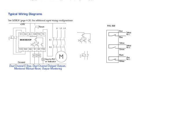
The center of the picture has selections from the diagram on the left. I am unfamiliar with the symbols used...

1. What kind of switch is that in the center bottom?

2. What are the symbols in the center top... F.E.T'.s?

3. Which are timed?

Link to more info re: safety relay
http://www.ab.com/catalogs/safety/prodtypepdf/ch4/4-46_4-47.pdf

The symbol on the right is a "switch" that is used with the relay on the left. It is obviously not just a normal switch because I cannot read through the normally closed contacts with an ohmeter.

4. What exactly is this switch?
http://www.ab.com/catalogs/safety/prodtypepdf/ch3/3-60_3-63.pdf

I don't know what terminology to use when something is not as it is represented on the drawings. I see on the prints from a job where these are used, that they are "hooked up in series" with other switches of the same kind.
.
5. If they are not switches, which it seems to me they are not, in the literal sense of the word, can they me hooked in series?... how many? Does it matter how many?

I have a big long rant I would like to unload , but I will spare you. The links I have posted are about as good as anything I was able to find re: these items. Surely there is better and more detailed information out there than this. If someone can point me to it, I will remember you at Christmas...


I won't send you nothin' , but I'll remember you..:)
 
Last edited:

petersonra

Senior Member
Location
Northern illinois
Occupation
engineer
It looks the switch has normal dry contacts to me. You should be able to ring through the safety NC contact IF the little actuation device is present.

It does look like the relay itself uses FET output devices for some reason. Should not make a whole lot of difference in operation. From the datasheet it appears the safety outputs are both delayed, while the aux contact is not.
 
Last edited:

realolman

Senior Member
It looks the switch has normal dry contacts to me. You should be able to ring through the safety NC contact IF the little actuation device is present.

.

That is certainly what the drawing seems to be representing, but I can't ring through anything on any two of the leads.

That's what made me think it is not a normal magnetic reed switch or something like that.:-?

I didn't try to hold the actuation device to the switch, because I thought the NC contacts, or at least ONE of the contacts somewhere should be closed when NOT in the presence of the magnet.
 

IMM_Doctor

Senior Member
That is a "Dual-Channel" monitored E-Stop Relay.

You will need an E-Stop Pushbutton with (2) N.C. (normally closed contacts)

The E-stop Button is shown on the left, it is wired to S11, S12 (one channel) and S21, S22 (second channel).

You can actually wire multiple e-stop buttons in series as long as each e-stop button has two contacts.

That is the crux of this device, it is looking to see if both channels agree with each other. It is also looking to see if both channels OPEN in sync and close in sync.

Power to the device is supplied via A1 and A2

The drawing is showing an external reset. If the e-stop is pressed, safety outputs of the unit are de-activated. Once your restore the e-stop button, you will also need to press the external reset pushbutton that is wired to S34.


K1 and K2 The square boxes wired to teminals 14 and 24 are the coils of a 4-pole contactor these two contactors must have "force-guided" contacts. The (3) N.O contacts are for power to the motor, the (1) N.C. contact is monitored also by the safety relay and wired to Y2. If the safety relay is off, it will NOT reset unless it sees voltage on Y2. This is ensuring that both of the safety power contactors are not welded shut.

This is a very safe system, as it is unlikeley that BOTH of the saftey contactors would FAIL on the same iteration. The system would not be able to be reset at the first point of failure of either of the safety contactors K1 or K2.

Y32 is merely a status output that can be fed to a superivory PLC or even a simple pilot light to indicat the status of the safety realy. OFF = Outputs disabled. On= Outputs enabled.
 

petersonra

Senior Member
Location
Northern illinois
Occupation
engineer
That is certainly what the drawing seems to be representing, but I can't ring through anything on any two of the leads.

That's what made me think it is not a normal magnetic reed switch or something like that.:-?

I didn't try to hold the actuation device to the switch, because I thought the NC contacts, or at least ONE of the contacts somewhere should be closed when NOT in the presence of the magnet.

I would try it with the actuation device present and see if either of the safety contacts works.
 

masterinbama

Senior Member
The reset will need to be a momentary contact and it needs to be pressed at the initial power up to put the relay in it's normal state. ( If my memory serves right me anyway)
 

ELA

Senior Member
Occupation
Electrical Test Engineer
That is certainly what the drawing seems to be representing, but I can't ring through anything on any two of the leads.

That's what made me think it is not a normal magnetic reed switch or something like that.:-?

I didn't try to hold the actuation device to the switch, because I thought the NC contacts, or at least ONE of the contacts somewhere should be closed when NOT in the presence of the magnet.

These sensors are more complicated than the simple schematic indicates.
It states that they "must" be used with a Sipha controller. The controller pulses the lines to monitor the sensor wiring for shorts. The controller then provides the "dry contact" output.
 

billsnuff

Senior Member
realolman

realolman

we use AB e-stop equipment. it took longer to configure it than it did to wire the entire machine. We actually had to get a rep on land line to explain the connections. once installed correctly, it works great. FWIW i have some AUTOCAD dwg files if you have a need. PM will work.

i think IMM-DR hit the nail on the head.
 

realolman

Senior Member
Maybe every one else knew this, but I didn't. The actuation device does need to be present to read the switches as it shows in the drawing.

I thought "normally" meant de-energized and without any outside influence (like a magnet).

IMM_Doctor, where did you get all this information? I have been unable to find nearly that much info.
 

IMM_Doctor

Senior Member
RealOlMan,

Are you de-bugging an existing installation, or are your selecting components for a new application.

You keep refering to a magnet? Is your intent to use the safety relay for perimeter guarding with magnet switches affixed to doors or guards?

If you are using magent switches at each door, there will need to be TWO at each door. Re: Channel 1 S11-S12 and Channel 2 S21-S22 MUST make and break at the same time.

I am comfortable with these relays as we install them on our machine control projects. The schematics look a little off-kilter to the layman, as the sybols used are more from the IEC European genre. When I CAD these relays into our prints, we use the "old" USA symbols for coils, contacts, PB's etc, for USA user friendly schematics.
 
Status
Not open for further replies.
Top