Shackled Designer
Member
- Location
- Decatur, AL USA
Greetings.
Suppose it is determined by a risk assessment that a safety circuit must achieve at least a SIL 2, PL d, Category 3 (EN 954-1) rating. Suppose also, that setup of the related equipment requires a monitored safety guard that can be open without disabling the safety output contactors provided that a three-position safety switch is engaged while the guard is open, but for not more than, say, 30 seconds continuously (so satisfying the OSHA requirement that a safety enable device not be used to permanently circumvent normal guarding). Naturally, there is also an E-Stop pushbutton involved in this safety system.
Now, normally in such a scenario, the designer would normally utilize a small safety PLC, since it is fairly simple to program a solution for this scenario with its several, connected devices and functional requirements. However, the boss (who remembers those happy times when the safety system consisted of an E-Stop, a reset pushbutton, a few general-purpose relays, and a master contactor) is trying to make the equipment more affordable and so questions whether the cost of a safety PLC is justified. He suggests that some cost might be saved if a safety-rated relay is instead used.
The designer does some more research and finds that among the myriad of safety relays on the market, there exist the several different functionalities needed for the circuit and proceeds to sketch up a wiring diagram involving four (4) safety relays:
Safety Relay 1 -- Door/Guard monitor
Safety Relay 2 -- 3-Position Switch monitor with time-limited usage
Safety Relay 3 -- E-Stop circuit monitor
Safety Relay 4 -- A Safety-rated Relay that monitors two separate dual-channel safety inputs and enables the safety outputs if either input pair is properly made (i.e. a logical safety OR circuit)
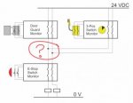
The boss sees that relays 1 through 3 are essential, but he asks why #4 is needed. Would it not be acceptable, he asks, to parallel the safety outputs from both the door guard monitor and the 3-position timed monitor into the power feed side of the E-Stop relay's safety output? (See the attached, primitive illustration.)
The designer questions whether parallel connections to the final relay infeed is acceptable, wondering whether the SIL2, Category 3 requirements could be met by such a circuit.
I suspect there is some written safety requirement somewhere for a parallel input situation, but I have been unsuccessful locating such documentation with safety relay examples since, I suppose, most designers would resort to a safety PLC if more than two or three safety relays are required, and most example scenarios involving two or more safety relay devices typically make use of simple AND logic for safety, a very straightforward, simple approach.
I welcome any comments on the question of whether a design meets the stated safety and functional requirements with just the three relays? A reference to any safety standard addressing such an arrangement would be very helpful.
Best regards,
Shack
Suppose it is determined by a risk assessment that a safety circuit must achieve at least a SIL 2, PL d, Category 3 (EN 954-1) rating. Suppose also, that setup of the related equipment requires a monitored safety guard that can be open without disabling the safety output contactors provided that a three-position safety switch is engaged while the guard is open, but for not more than, say, 30 seconds continuously (so satisfying the OSHA requirement that a safety enable device not be used to permanently circumvent normal guarding). Naturally, there is also an E-Stop pushbutton involved in this safety system.
Now, normally in such a scenario, the designer would normally utilize a small safety PLC, since it is fairly simple to program a solution for this scenario with its several, connected devices and functional requirements. However, the boss (who remembers those happy times when the safety system consisted of an E-Stop, a reset pushbutton, a few general-purpose relays, and a master contactor) is trying to make the equipment more affordable and so questions whether the cost of a safety PLC is justified. He suggests that some cost might be saved if a safety-rated relay is instead used.
The designer does some more research and finds that among the myriad of safety relays on the market, there exist the several different functionalities needed for the circuit and proceeds to sketch up a wiring diagram involving four (4) safety relays:
Safety Relay 1 -- Door/Guard monitor
Safety Relay 2 -- 3-Position Switch monitor with time-limited usage
Safety Relay 3 -- E-Stop circuit monitor
Safety Relay 4 -- A Safety-rated Relay that monitors two separate dual-channel safety inputs and enables the safety outputs if either input pair is properly made (i.e. a logical safety OR circuit)
The boss sees that relays 1 through 3 are essential, but he asks why #4 is needed. Would it not be acceptable, he asks, to parallel the safety outputs from both the door guard monitor and the 3-position timed monitor into the power feed side of the E-Stop relay's safety output? (See the attached, primitive illustration.)
The designer questions whether parallel connections to the final relay infeed is acceptable, wondering whether the SIL2, Category 3 requirements could be met by such a circuit.
I suspect there is some written safety requirement somewhere for a parallel input situation, but I have been unsuccessful locating such documentation with safety relay examples since, I suppose, most designers would resort to a safety PLC if more than two or three safety relays are required, and most example scenarios involving two or more safety relay devices typically make use of simple AND logic for safety, a very straightforward, simple approach.
I welcome any comments on the question of whether a design meets the stated safety and functional requirements with just the three relays? A reference to any safety standard addressing such an arrangement would be very helpful.
Best regards,
Shack