Designer101
Senior Member
- Location
- California
- Occupation
- Solar and ESS Designer
3 SolarEdge single phase inverter 11.4 kw is used to make three phase connection
SOME questions I am confused
I thought the wiring diagram shows 120/240 3 phase 4 wire delta( high leg) in the main panel
our guys at the site says they didn't measure any unusual voltage ( L- N to be 208 VOLTS)
they Said they measure
208 208 208 and 120 120 120
but I designed it to be 240 240 240 and 120 120 208 thinking high leg and skipping high leg
so this means the connection at main panel depends on what's coming from transformer ?? it has nothing to do in the main panel side and main panel as such can be configured to any configuration 120/208 3 phase 4 wire wye or 120/240 3 phase 4 wire delta??
also next question
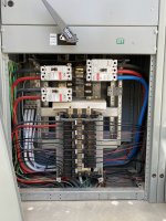
Looking at the pictures of main panel
there are two pole breaker at the bottom panel this Means those two pole breaker will read 208 volts when measure between two phases if connected as 120/208 3 phase 4 wire wye??
Please look pictures attached.
SOME questions I am confused
I thought the wiring diagram shows 120/240 3 phase 4 wire delta( high leg) in the main panel
our guys at the site says they didn't measure any unusual voltage ( L- N to be 208 VOLTS)
they Said they measure
208 208 208 and 120 120 120
but I designed it to be 240 240 240 and 120 120 208 thinking high leg and skipping high leg
so this means the connection at main panel depends on what's coming from transformer ?? it has nothing to do in the main panel side and main panel as such can be configured to any configuration 120/208 3 phase 4 wire wye or 120/240 3 phase 4 wire delta??
also next question
Looking at the pictures of main panel
there are two pole breaker at the bottom panel this Means those two pole breaker will read 208 volts when measure between two phases if connected as 120/208 3 phase 4 wire wye??
Please look pictures attached.