SBJ, SSBJ, MBJ

Status
Not open for further replies.
If you have a transformer and you connected your system bonding jumper (from XO to transformer case) and then connected a supply side bonding jumper (from transformer case to main panel) would you still use a main bonding jumper in the main panel? I don't think you would (grounding conductor would become a current caring conductor).
But this brings up another question which method would you use, the MBJ at main panel or SBJ, SSBJ? My hypothesis is the distance between transformer and main panel would determine the method.

So is the system bonding jumper and main bonding jumper are the same thing?
 
A main bonding jumper is installed at the first disconnect of a service. A system bonding jumper is installed at the source or the first disconnect, but not both, of a Separately Derived System. The issue of where the system bonding jumper is installed is strictly a design issue. There is no real reason to install it in one location or the other.
 
Although a SBJ and a MBJ are similar in purpose the NEC provides a distinguished difference between them by calling them different things.
 
I think others are not answering the question that was asked. True you have a choice of bonding the separately derived system either at the transformer or at the first disconnect. But since OP mentioned supply side bonding jumper along with the comment about the grounding conductor becoming a current carrying conductor, I think he was asking a different question than what was answered.

You must have a main bonding jumper at the service, and you must have a system bonding jumper for a separately derived system. No current flows between the primary and secondary circuits of the transformer. If current does flow between them you do not have a separately derived system you have an autotransformer.

A separately derived system is in many ways like a service, you need a point that is grounded for all the same reasons we ground a point at the service. But primary windings of the transformer have no electrical connection to the secondary windings and that is why it is called a separately derived system - it is a system that essentially is separate from the primary, and has no voltage reference to the primary (until we do ground a point of the secondary).
 
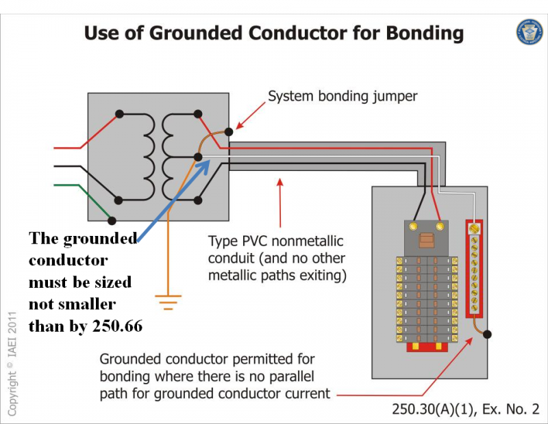
Yes one can install the system bonding jumper at the XO of the SDS and also install a bonding jumper at the disconnect but only if there is no current carrying path between the SDS and the first disconnecting means. This would require that a non-metallic raceway be installed between the two and no equipment grounding conductor (supply side bonding jumper) be installed either.

250.30(A)(1) Exception No. 2: A system bonding jumper at both the source and the first
disconnecting means shall be permitted if doing so does not establish a parallel
path for the grounded conductor. If a grounded conductor is used in this manner,
it shall not be smaller than the size specified for the system bonding jumper
but shall not be required to be larger than the ungrounded conductor(s). For the
purposes of this exception, connection through the earth shall not be considered
as providing a parallel path.
IMO, the exception you quoted should be removed from Code for new installations. A supply-side bonding jumper is required without exception. Thus there will always be a parallel path for the grounded conductor—the SSBJ—whenever an SBJ is installed at both locations.
 
Last edited:
IMO, the exception you quoted should be removed from Code for new installations. I say a supply-side bonding jumper is required without exception. Thus there will always be a parallel path for the grounded conductor?the SSBJ?whenever an SBJ is installed at both locations.

I was trying to imagine an installation where you would use this exception. So when doing so would you need to have a SSBJ between the transformer and the disconnect?
 
I was trying to imagine an installation where you would use this exception. So when doing so would you need to have a SSBJ between the transformer and the disconnect?
No .

neutralisbondingSDS_zps3005951f.png


Refer to Section 250.30(A)(1) Ex. No. 2 for this allowance to use the grounded conductor for bonding at both ends between the source and the first system equipment enclosure.

This is an alternative method of bonding that utilizes the grounded conductor and allows a system bonding jumper to be bonded to the source enclosure and also at the first system disconnect or overcurrent device enclosure where doing so does not create a parallel path for current that would be returning to the source over the grounded conductor. (notes taken from slide)
 
Last edited:
Maybe I misunderstood what was being asked? I don't disagree with anything Don said, just didn't think it was the answer to the question asked.

You might be right. We won't really know to the poster of the OP checks back in.
 
I was trying to imagine an installation where you would use this exception. So when doing so would you need to have a SSBJ between the transformer and the disconnect?

No .


Refer to Section 250.30(A)(1) Ex. No. 2 for this allowance to use the grounded conductor for bonding at both ends between the source and the first system equipment enclosure.

This is an alternative method of bonding that utilizes the grounded conductor and allows a system bonding jumper to be bonded to the source enclosure and also at the first system disconnect or overcurrent device enclosure where doing so does not create a parallel path for current that would be returning to the source over the grounded conductor. (notes taken from slide)
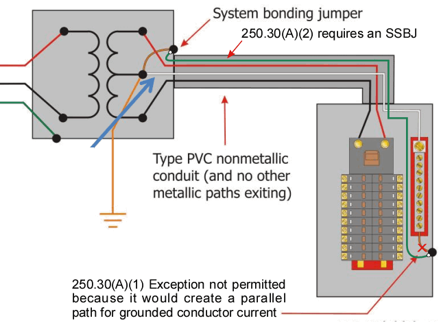
Actually, yes... under 2011 NEC, since we are using the term Supply-Side Bonding Jumper. Under 2008 NEC and prior editions, the term used was Equipment Bonding Jumper, and the method depicted was permitted. However, under 2011 NEC, a supply-side bonding jumper is required to be installed... without exception. See 250.30(A)(2) of respective editions. You cannot install an SBJ in both enclosures.
 
Last edited:
Actually, yes... under 2011 NEC, since we are using the term Supply-Side Bonding Jumper. Under 2008 NEC and prior editions, the term used was Equipment Bonding Jumper, and the method depicted was permitted. However, under 2011 NEC, a supply-side bonding jumper is required to be installed... without exception. See 250.30(A)(2) of respective editions. You cannot install an SBJ in both enclosures.

So you would install a smaller conductor (SSBJ) in parallel with the neutral?
 
So you would install a smaller conductor (SSBJ) in parallel with the neutral?
The SSBJ is sized per 250.66... which could be smaller than the neutral... but it is not in parallel with the neutral. (I think of it as a large EGC)

The SSBJ would be in parallel with the neutral if you installed an SBJ in both transformer and first diconnect enclosures... but that is not permitted, even by the exception that supposedly permits dual SBJ's.
 
If you go back to Mike's original graphic in post #9 why would a SSBJ be required the panel has a bonded neutral?
 
If you go back to Mike's original graphic in post #9 why would a SSBJ be required the panel has a bonded neutral?
I don't make the rules and its pointless to speculate. If you really want to know the reason, perhaps if you look up the ROP/ROC for the change to 250.30(A)(2) in the 2011 NEC you'll be enlightened... :p
 
May I interject, since we have now answered the OP, I am tired of the alphabet soup of ill defined terms the NEC tossed into art. 250.

IMO they took a concept that is simple in principle and up-sized confusion by adding more letters to describe doing the same thing.
 
Here's some clarification for the 2014 NEC:

________________________________________________________________
5-85 Log #3255 NEC-P05
Final Action: Accept in Principle
(250.30(A)(1) Exception No. 2)
________________________________________________________________
Submitter: Mark R. Hilbert, MR Hilbert Electrical Inspections & Training
Recommendation: Revise text to read as follows:
Exception No. 2: For installations made in compliance with previous editions
of this Code that permitted such connections, A a system bonding jumper at
both the source and the first disconnecting means shall be permitted if doing so
does not establish a parallel path for the grounded conductor. If a grounded
conductor is used in this manner, it shall not be smaller than the size specified
for the system bonding jumper but shall not be required to be larger than the
ungrounded conductor(s). For the purposes of this exception, connection
through the earth shall not be considered as providing a parallel path.
Substantiation: This is one of two proposals I have submitted to allow CMP-
05 to consider an issue that resulted from the revision and reorganization of
250.30 in the last cycle. The other proposal is submitted to 250.30(A)(2). If this
proposal is accepted, my proposal to 250.30(A)(2) should be rejected.

Exception No. 2 to 250.30(A)(1) permits a system bonding jumper to be
installed at the source and first disconnecting means if doing so does not
establish a parallel path for the grounded conductor. However, the current text
in 250.30(A)(2) essentially eliminates the application permitted by Exception
No. 2. If it was the intent to not allow the grounded conductor to be used in
this manner (as the ground fault return path where doing so does not establish a
parallel path) then this proposal could be accepted and my proposal to
250.30(A)(2) would be rejected.
Panel Meeting Action: Accept in Principle
Revise the exception to read as follows:
250.30(A)(1) Exception No. 2
Exception No. 2: If a building or structure is supplied by a feeder from an
outdoor transformer, Aa system bonding jumper at both the source and the first
disconnecting means shall be permitted if doing so does not establish a parallel
path for the grounded conductor. If a grounded conductor is used in this
manner, it shall not be smaller than the size specified for the system bonding
jumper but shall not be required to be larger than the ungrounded
conductor(s). For the purposes of this exception, connection through the earth
shall not be considered as providing a parallel path.
Panel Statement: See the panel statements on Proposal 5-84 and Proposal
5-88. The revised text provides for the limited case where the grounded
conductor can be bonded at the source of a separately derived system and in a
building or structure served and continues to prohibit parallel paths. The panel
action on proposal 5-88 allows the elimination of the supply-side bonding
jumper where the grounded conductor can serve as the ground fault return path.
Proposal 5-244c adds an exception to 250.32(B) to require the grounded
conductor to be connected to the equipment grounding conductors, grounding
electrode conductor and the first disconnecting mean enclosure when this
exception is used.
Number Eligible to Vote: 16
Ballot Results: Affirmative: 16
 
I think what Smart is talking about is the verbiage found in 250.30(B) which is different than what it was in the 08 edition.

08 says; (2) Equipment Bonding Jumper Size. Where an equipment bonding jumper of the wire type is run with the derived phase conductors from the source of a separately derived system to the first disconnecting means, it shall be sized in accordance with 250.102(C), based on the size of the derived phase conductors.
And the 11 cycle says
(2) Supply-Side Bonding Jumper. If the source of a separately derived system and the first disconnecting means are located in separate enclosures, a supply-side bonding jumper shall be installed with the circuit conductors from the source enclosure to the first disconnecting means. A supply-side bonding jumper shall not be required to be larger than the derived ungrounded conductors. The supply-side bonding jumper shall be permitted to be of nonflexible metal raceway type or of the wire or bus type as follows:

But in the exception of (1) in the 11 cycle it clearly states
Exception No. 2: A system bonding jumper at both the source and the first disconnecting means shall be permitted if doing so does not establish a parallel path for the grounded conductor. If a grounded conductor is used in this manner, it shall not be smaller than the size specified for the system bonding jumper but shall not be required to be larger than the ungrounded conductor(s). For the purposes of this exception, connection through the earth shall not be considered as providing a parallel path.
Which states that it is permissible as long as there is no parallel path, but (2) requires the installation of the SSBJ therefore not allowing the bonding at both ends. I think that the exception of (1) will trump (2) and the installation is allowed but who am I?
 
Status
Not open for further replies.
Top